-
24th April 2017, 04:58 PM
#1
How to make sills.
MAKING LAND ROVER SILLS
by Charlie Myres
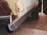
The flat sill-panel below the doors and body on Series 2 and 3 Land Rovers often needs replacing because it has been badly dented from off-road driving, or because someone has taken them off.
Whilst these are available commercially, it is cheaper to make your own and also a lot of fun. Tools needed are not expensive and some can be made out of wood, by anyone with a desire for making things.
Below is a photograph of a sill I made for my S3; the whole process, including making a drawing, took me about 2 hours.
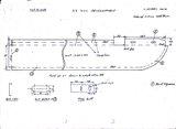
The Drawing: Before you start cutting any metal, always make a sketch on a piece of A4 paper of the panel laid out flat; this is called the "development". The development is essential, because it gives you the total size of the metal required this is called the "cutting-size". Sizes can be measured off an old panel, or off a friend's car; don't forget to measure the metal thickness with a vernier caliper, or micrometer. Useful production notes can also be written on the sketch such as, "fold this bend first".
The sketch also has fold-lines marked on it and sometimes a pictorial sketch in a corner, to help the viewer visualise the finished product. Always title your drawing and write your name on it, and if you think you may ever need to make another one, file it in a folder in the shed. For the sill, the folding is reversed, to make left-hand and right-hand parts.
Below is a scan of the sketch I made for the sill.
Material: Not all aluminium is the same!
In Australia aluminium sheet from the 5000 series is the best to use, because of its workability and strength. Have a look at your local supplier's website, or ring them and explain that you need an alloy that can be annealed multiple times. This is important because some aluminium alloys can only be annealed once and then they age-harden; some alloys are hard when you receive them and it is very difficult to work them at all! Old road-signs are an example of the last problem and are useless for this type of project. Make sure that you order a sheet, which is close to the same thickness as the original part. Thicker material is harder to bend and on the curved part of the sill, is harder to shape for no gain. I use 5005 from Midalia Steel.
Time now to pause and consider what "annealing" and "age-hardening" means and how to work the 5005 aluminium. Some people call 5005 "half-hard"; what this means is that you can bend it quite comfortably, but it will work-harden as you bend it. This is not usually a problem, unless you want to keep working the bend line, which will cause the metal to crack. Think of it as the same process as bending a piece of wire in your hands back-and-forth until it breaks, when the wire has work-hardened.
On the sill, forming the curved flange at the front will cause work-hardening, at which point the aluminium will refuse to cooperate and cannot be shaped. When this happens the metal must be annealed, which means to make it soft again. Annealing aluminium is very easy; get a cake of soap, wet it and rub it on the part of the sheet, which has gone hard. Using an LPG torch or an oxy-acetylene flame heat the soaped part carefully with the end of the flame, at the same time constantly keeping the flame moving. If you keep the flame still, the aluminium will melt, so keep it moving! When the soap turns black, the aluminium has undergone a crystalline restructure and it is now soft enough to work. If the soap is brown, keep heating until it turns black.
Some aluminium alloys age-harden; this means that after annealing – sometimes taking 24 hours or longer – the crystalline structure changes and the alloy becomes hard again. I don't think 5005 does this, but if the panel you annealed yesterday has gone hard, that is what it will be. It is usually best-practice to anneal and then work the metal as soon as it has cooled.
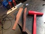
Tools: Aluminium, when it is hammered with steel tools marks badly; to avoid this, wooden or plastic tools should be used, or sometimes the metal can be protected from a hammer blow by a wooden or metal block, or plate. Even wooden tools will mark the aluminium, so all sharp edges must be removed and filed, or sanded to a radius. Most of the wooden tools can be made at home using Australian hardwood; a good source is old wooden handles. Never throw away a broken block-splitter handle!
A list of tools you will need to make this project is below;
• LPG torch or oxy.
• A folding brake; or a flat bench to which the work can be clamped; or some angle-iron clamps and a vice; or access to someone who has a bending-brake.
• Rule; scriber, or 0.5mm felt-pen.
• Tinsnips; bench shears, or electric shears; or access to a business with a guillotine. Tinsnips are all that is needed if you buy the metal pre-cut.
• Heavy club-hammer for bending; blocks of wood for bending; MDF, 12mm plastic, or hardwood for forming the curved end.
• A piece of soap pinched from the bathroom.
• Wooden mallet, or a length of hardwood about 50mm x 25mm x 300mm.
• A suitable dolly for the curved end; or a piece of hardwood accurately cut to the profile and sanded smooth.
• A panel-beater's body file and flipper.
• A spot welder capable of welding aluminium; or Sikaflex adhesive; pop riveter and aluminium rivets (optional).
• Electric drill and bits.
• Flat cold chisel and hammer.
Method:
1. Double check your development to make sure that your dimensions are correct and that the shape is correct.
2. Mark out the cutting-size on the aluminium using the scriber and rule, or a fine felt pen not bigger than 0.5mm. I prefer a scriber, because sheet-metal work demands exacting accuracy, if you want it to look nice and fit perfectly.
3. Cut the metal to size. If you go to an engineering business, they can cut it for you, but you pay for it. If you plan to make lots of sills, it may be easier and certainly cheaper, to cut them yourself. I use electric shears to rough it to size – about 10mm too big – and then I cut it exactly to size, using bench shears and snips. I do it this way because my shears distort the metal as it cuts and it is impossible to cut a straight line.
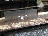
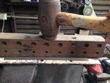
4. Mark the detail onto the blank using the scriber and rule. Now is the time to consider making the slotted holes; if you fold the bends too soon it can be difficult to drill holes later. The photo below shows a piece of scrap in which I have punched two holes to represent the slots in the original panel.
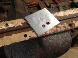
If you don’t have a punch, the holes can be drilled; to make the holes round, sandwich the metal between two pieces of timber such as MDF and clamp securely. A small hole in the top piece of MDF – about 4mm in diameter – allows the parts to be aligned with the punch mark on the panel.
Photo below;
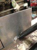
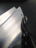
The work is then clamped in the angle clamps and using a sharp cold-chisel the waste can be removed with two cuts. Note the angle of the chisel, with the bevel sitting flat on the clamp; this is most important, as it stops the panel getting bent, which would happen if the cutting edge was raised higher. The cold-chisel will leave a burr on the reverse side, which can be removed with a file, or by sanding with a flap-wheel.
More to follow.
-
24th April 2017, 05:54 PM
#2
Part 2.
Photo below shows the waste nearly removed.
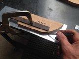
5. For the curved part I use a cardboard template traced from the original panel; this can then be used to make a steel template, which will last longer. Add a line past the curve using the rule and scriber.
Photo below; using the inner hammer-form as a marking template and scratching the curve with a scriber.
• Label fold lines with an instruction e.g. "Fold up." This helps when you don't want to accidentally make two right-hand ones.
Cut off the waste material. There are several ways of doing this, all of them work; some are easier on the hands than others, some are easier on the wallet.
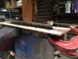
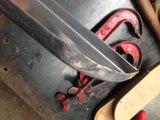
• For straight lines I prefer the bench shears, these are expensive to purchase but easy to use. They can also be used to cut curves. If you leave about 2mm of waste outside the curve and cut the waste off as in the photo below, then the remaining waste can be easily removed with the shears; the same technique applies to using snips.
• Use snips; which can be hard on the hands but are cheap to buy. In the photo above, most of the waste has been removed as straight cuts using the bench shears; the 2 to 3mm of waste left, can then be easily removed with snips.
• Fold the straight bends. This can be easier said than done; you may have noticed on my drawing that there are numbers within a circle pointing to individual fold lines; these represent the order of bending. There is also a view of the end of the panel, to help me work out which bends need to be done before the others. The reason being, that sometimes it is impossible to make a second bend because the work cannot be clamped, because the first bend gets in the way and this depends on what type of bender or facilities you have for folding. In the following photos I have shown different methods of bending that you might use; you need to decide what suits your budget and then work out the order of your bends to suit your equipment.
First photo below shows a piece of steel in the angle-clamps, clamped in the vice and with a G-clamp as well. The steel has been bent using a block of wood and a hammer as in the photo after it. It can be bent with a hammer alone but that will leave hammer marks on the surface; in addition, the hammer can only bend a short distance at a time, so the metal will be stretched unevenly producing a wavy or curved edge. This can be corrected afterwards with a planishing hammer, but it is all extra effort for little gain. Exactly the same process is used to bend aluminium.
More to follow.
-
24th April 2017, 06:26 PM
#3
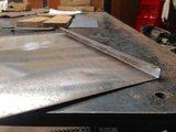
Photo below; the completed bend is now clamped to the bench with a 12mm length of flat bar clamped on top of it. I am only using steel sheet, because I didn’t have any aluminium to demonstrate on. The two folds replicate what is on the top of the sill. For a long fold, rather than the short practice one I am doing, a heavy piece of bar, or angle can be clamped to the bench as in the photo and both bends folded with a hammer and block of wood. The only disadvantage with this method is some mild stretching. which will need to be fixed. The best method, is to use a sheet metal folder for guaranteed accuracy.
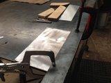
Photo below; how the steel folds turned out, they are not at 90 degrees due to elasticity in the metal and the second bend done on the bench, has more radius than the one done in the angle clamp. The bends can be dressed with a hammer and dolly but this is extra work.
Picture below shows my dummy panel in aluminium, after having the first fold bent in the magnetic-brake. I could have done the second and third folds in it as well, but I did the second one in the angle clamps for the sheer fun of it! In any case the metal was too small to fit the third fold on, so this piece is really for demonstrating turning-a-flange on a curve. I have a manual brake as well, which I made myself, it is good for folds but not as versatile as the magnetic one.
Whatever method you use, try to avoid making a straight fold on the curve, as this will make it harder to shape the curve later.
• Fold the curved flange – now the interesting part starts! Shape a piece of MDF, or similar, using the curved template and check that it fits inside the sill. When it is a good fit along the curved fold-line, use it as a template to make another one, this will sit on the outside of the panel sandwiching the metal in between and is called a hammer-form.
Photo below, shows left to right; panel sandwiched between two bits of MDF and clamped to the bench; wooden beater for outside curves; wooden beater for inside curves; plastic bossing mallet filled with lead shot. I used the mallet and the straight beater to turn the flange. The beater for inside curves was not used on this project, but it would be essential on for the wheel-arch lip on the wing, for example.
More to follow.
-
24th April 2017, 06:48 PM
#4
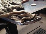
Clamp the hammer-form firmly in a vice, or clamped to a bench top and beat the aluminium with glancing blows using a wooden, or plastic mallet, or a wooden beater. You will quickly discover that the aluminium puckers and that after a while it becomes harder to work. This means two things; firstly the metal needs annealing and secondly the puckers need to be shrunk.
• Annealing has been explained previously, but in this context the metal must be removed from the hammer-form and heated separately. To prevent the flat part of the panel deforming in the heat, I lay an old towel, or rag soaked in water on the flat part. When the panel is cool, return it to the hammer-form.
Photo below; shows the wet rag and the blackened soap on the flange, which has been turned this far before annealing, using the mallet.
• To shrink the pucker after annealing, use a wooden mallet and beat the narrow end of the pucker and progressively work your way down to the high end. You will see and feel the soft metal move immediately as you force the pucker into itself. Search youtube for videos on tuck-shrinking. Repeat the process on all of the puckers. When I made mine, I had to anneal one place twice, to get the metal to shrink enough to fit the hammer-form. On this practice one, I had to anneal 3 times to get rid of the big pucker in the photo above.
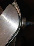
• When the flange has been turned and shrunk, remove the panel from the hammer-form and file the curved face looking for high and low spots. Panel beat as required with flipper, hammer and dolly. In the photo below I am using a toe-dolly to help beat the low spots up with a planishing hammer. Later on I used a piece of 25mm round bar as a dolly, held in the vice and used the hammer to raise the stubborn lows.
• Mark the width of the flange; you may have noticed that after shrinking the puckers, the flange has grown too wide. Remove waste with small snips, or sand with a flap-wheel on the angle grinder. In the photo below; the increased width of the flange is noticeable where I have shrunk the pucker. Instead of using the above methods to reduce it, I experimented and used a dreadnought file, with the worked clamped to the bench, to remove the excess metal; it worked well.
• Mark-out and make the mounting brackets; the slots can be made by drilling the end holes and removing the waste with the angle clamps and a small cold chisel. The same method can be used on the sill upper-flange, as described previously.
• Locate the mounting brackets on the chassis and transfer the measurements to the sill. I used Sikaflex adhesive to glue the brackets in place, clean the panel with acetone first and rough the metal with coarse abrasive as well. Alternatives are spot-welding – as per the original – and pop-rivets.
Job done!
Photo below; curved flange filed and sanded. If I was making lots of these I would make a polished steel hammer-form to go inside the sill, which would double as a dolly.
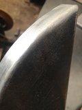
Depending on how you want the finished product to look, remember that aluminium scratches easily, so protect it as much as possible when working it; use wooden, or aluminium protectors when clamping; make sure everything is clean before clamping.
Be creative! If the tool isn't working well, make something that will. If it works for you, then it is the right way!
Cheers Charlie
-
24th April 2017, 07:12 PM
#5
GREAT!
Thanks Charlie, I'll be using this!
Peter.
Tags for this Thread
 Posting Permissions
- You may not post new threads
- You may not post replies
- You may not post attachments
- You may not edit your posts
-
Forum Rules
Search AULRO.com ONLY!
|
Search All the Web!
|


 Reply With Quote


Bookmarks