

 Reply With Quote
Out of which model/year? The L322 (02 onwards) has an ecu to control them. Not sure what the P38 seats had.

 Master
I haven't had any luck searching for wiring information on Rangie electric seats. I bought a pair to install into a truck cabin for better touring comfort.
The drivers seat as supplied by the wrecker seems to have incomplete wiring, as there are about 5 male connectors with nowhere to plug in to. On the passenger seat, these plug into matching female connectors an seem to complete the communication with motors, switches, relays, etc.
I gather there could have been a control unit box attached there. Do I need to source that too? Any help or reference to earlier threads on the wiring & especially retro-fitting to other vehicles would be appreciated, please.
Cheers
Brid
Super Moderator & CA manager
SubscriberOut of which model/year? The L322 (02 onwards) has an ecu to control them. Not sure what the P38 seats had.
If you need to contact me please email homestarrunnerau@gmail.com - thanks - Gav.
ChatterBox
SubscriberIf you're talking late classic electric seats, the driver's seat has a memory function controlled by an ECU, whereas the passenger seat is controlled only by the switch so I suspect that's the difference. You could use the passenger seat as a guide and rewire the driver's seat the same way for manual operation only, might get very complicated wiring in a memory seat ECU. On my 94 rangie the memory function operates the mirrors as well.
YarnMaster
SubscriberIf you can determine the model(s) from whence the seats came, a detailed study of RAVE will give you all the circuits, connections, photos of said connectors and their pinouts.
BTW.. I didn't realise until a chance discussion with a design engineer a few years ago (back of the plane on a Qantas flight!) just how much research went into seat design in modern vehicles to ensure they were "compliant" with the vehicle suspension. For example, on a rough road if the seat is not in sync with the suspension response you get the effect of passengers getting a rough(er) ride because the wrong 'bounce factor' in the seat springs/foam density etc.
I suppose some older truck seats aren't all that sophisticated, so any improvement may be welcome... but the above may also indicate why the expected level of improvement in comfort from changing seats is not always met...
MY99 RR P38 HSE 4.6 (Thor) gone (to Tasmania)
2020 Subaru Impreza S ('SWMBO's Express' )
2023 Ineos Grenadier Trialmaster (diesel)
Master
What the others have said.
the ecu's for a classic cost a bomb if you can find one and the memory battery tends to leak and destroy the circuit board as mine did. The ecu is normally located under the drivers seat clipped into the subframe.
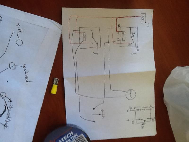
The simplest and most cost effective way for you to get the, to work is to wire up some relays as I did.
2 relays required for each motor so that you can switch the polarity. Then just wire up the switch that's on the inside of the seat to trigger each corresponding relay.
I originally found a wiring diagram someone drew up on another forum but found that his wire colours were incorrect for my 93 LSE. So I just ignored the colours and used a multimeter to work out which wire did what on the switch. The motors themselves are easy as obviously one 2 wires go to each of them but they are all yellow and green so just give them power and earth one by one and jot it down on a notepad.
The relays is used were just normal 5 pin relays from jaycar, wired up so relay gives the motor earth to both wires then the relay just triggers one earth to switch to positive.
I chopped the harness on the ecu end so I could still plug in a memory ecu if I came across one for cheap later on and it kept the wiring neat and original looking as the relays just about fit into the original ecu box. Use the one live and one earth feed from the original loom for all the relays and you should be good.
If you get stuck drop me a pm and ill give you my number so can talk you through it with my setup in front of me.

 Posting Permissions
| Search AULRO.com ONLY! |
Search All the Web! |
|---|
|
|
|
Bookmarks