
Originally Posted by
Blknight.aus

My bad missed a step in my haste to write it up for you, Relevent section in blue below missing step in red
Theres also a couple of obvious omissions in there but if you're at the stage of doing liners in an engine you should be able to spot the shortfalls of the writing and run with the intent.
(no, its not my best set of instructions ever so no, I wont be offended if they dont make complete sense and you need them rewritten)
And I've just re-read your post, you get it easy.
when it comes to the stages of machining.....
Machine an aligning plate that is the ID of the lower liner support, give it a lick with some sand paper (you want it not quite press fit, it should sit there with a coating of light oil/coolant as adhesive) then bore the center to make a post hole for the guide post
machine your guide post to the ID-5 thou of the liners you have then cut the step to support the driver and a post for the lower aligner
Machine the OD of the driver to id-5 thou of the liner supports
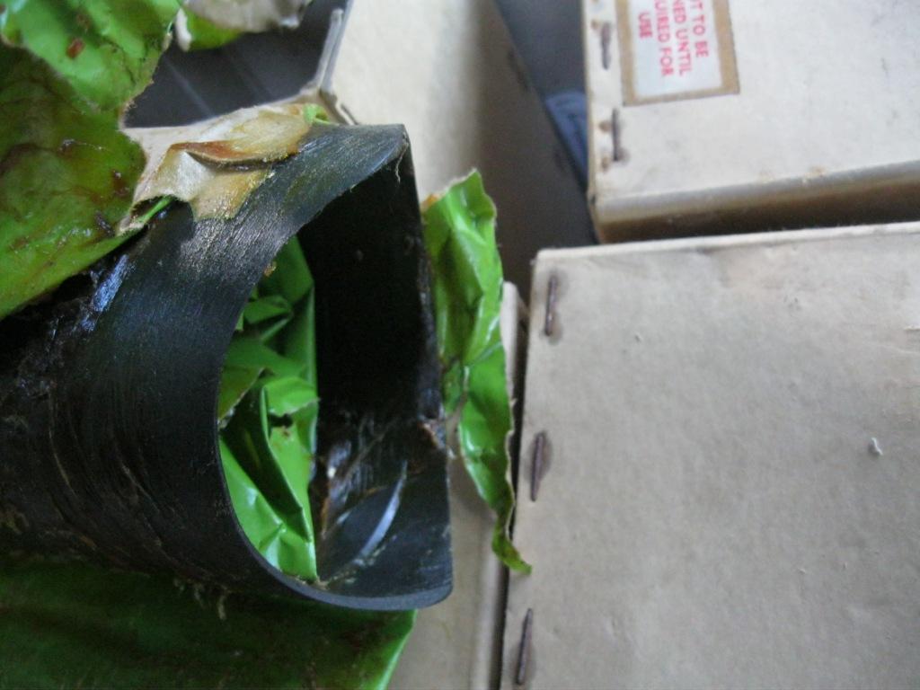
stand the driver on its end, drop the guide post in then drop the liner over the guide post, wrap it tightly in cardboard then trace out the face of the liner.
remove the liner and the cardboard, cut out the cardboard. Replace it onto the driver and mark the driver.
Cut and clean the driver to suit replacing it onto the guide post and using a blued liner to check your work.
Ally is a great medium for doing this with, if you are concerned with the post changing position too much after the guide post drives the aligner out of you can either make one up in the form of a C as per the previous post with something of similar wall thickness to support the post but realisitcally once the liner is in the first support it should just keep working its way down squarely if you apply the pressure evenly.
If you want to go old school with it, just make the driver up, 5 thou undersize of the liner supports, dome the top of it and beat it in with a hammer.


 Reply With Quote
")


Bookmarks