

 Reply With Quote
I found, somewhere on defender2.net iirc, For the black plug:
1 - power in
2 - dash illumination
3 - not used
4 - switch - power out to accessory
5 - earth
The numbers are printed on the plug, small tho.
I am not sure about the white plug.

 Master
Hi, I was at a pick a part the other day picking up parts for Dads Ford and came across a striped disco and had a descent and hazard switches still in dash, which I picked up for $5.
I want to use them to switch new work lights on my defender where I have a couple of free spots on dash. I will have to cover the icons though.
Does anyone know the pin configuration on these switches.
Thanks in advance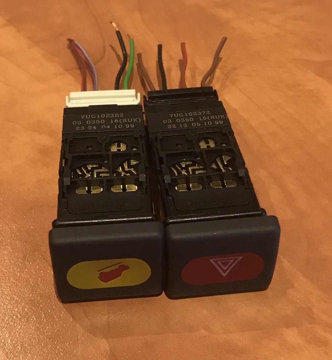
Wizard
I found, somewhere on defender2.net iirc, For the black plug:
1 - power in
2 - dash illumination
3 - not used
4 - switch - power out to accessory
5 - earth
The numbers are printed on the plug, small tho.
I am not sure about the white plug.
TopicToaster
Supporterthe 'fog light switches' on the dash pod are great for controlling lights. ie. you don't need to mod the fascias!
You probably already have some blanks you could replace them with.
I've fitted a front fog light switch to control my led bar.
I think Simon's reply is correct, middle one not used(vague recollection when I fitted my fog light switch).
I just checked power in/out with a multimeter to determine what each wire did/was.
Strangely tho, I had a quick peek at RAVE's electrical circuit diagram, and they show a red/brown wire for power in to the switch but list it as pin 2 on the connector.
And then a light green/red wire from pin 1 on the connector to the BCU!
Earth on pin 4.
Then if you trace back to C0096, it only shows 3 wires(page 258 RAVE electrical library), and again LtG-R/Red-Brown/Black.
Yet your switch(and the one I have) show 4 wires .. different colours on some lines!
Arthur.
All these discos are giving me a heart attack!
'99 D1 300Tdi Auto ( now sold :( )
'03 D2 Td5 Auto
'03 D2a Td5 Auto
Master
Many thanks for the great info.
I will set up my power supply and test wire with relay and a globe to make sure it is right
Cheers
YarnMaster
To make them trigger a relay and light up in the dark you have to connect them as follows:
Hazard switch pins: 1 - switched earth output, 2 - switched live from lighting switch input, 4 - earth, this switch was conceived to switch on earth so the relay must have direct ignition live on it and you switch the earth to it's coil
HDC switch(this one works on live), pins: 1 - ignition live input, 2 - earth, 4 - switched live output, 5 - switched live from lighting switch input
Discovery Td5 (2000), manual, tuned
Master
Many thanks for clarifying.Originally Posted by sierrafery

I just put together a quick sketch on wiring using HDC switch based on your description. Not sure about the Hazard though.
What do you think?
HDC Driving Light CCT.jpg
REVISED DRAWING
Also, a couple of years ago my uncle bought me a couple of these switches YUG000470LNF and YUG000540LNF as per photo from UK, and wired up a diagram for roof rack driving lights and work lights using these but havent been able to do anything yet.
Just need to confirm wiring for correctness and if correct other members on this forum can use these for future reference.
Many thanks
YUG000470LNF YUG000540LNF.jpgDriving Light CCT 006.jpg
Last edited by ProjectDirector; 6th May 2018 at 08:34 AM. Reason: submitted revised drawing
TopicToaster
SupporterI'm not an expert on electrics(in fact far from it), but I would have thought that a single 40A relay would be more than enough to run 4x70W(280) total power requirement.
That is, keep it as simple as possible to minimise the number of points of failure.
Arthur.
All these discos are giving me a heart attack!
'99 D1 300Tdi Auto ( now sold :( )
'03 D2 Td5 Auto
'03 D2a Td5 Auto
Master
Agree, I was just being too conservative. Each light has input current of 6.7 amps x 4 ~27 amp total.
I will modify, thanks for feedback
Master
Thanks for your contributions guys.
Last night I wired up all circuits (except the Hazard switch) on test bench and worked perfectly fine.
One interesting observation, the YUG000470LNF rear demister I think, even though the pin 2 was not connected the tell tale led was actually turning on while switch on, bonus one less connection.
Cheers
Wizard
Pin 2 is so the logo glows when you have the headlights on, not the red LED
| Search AULRO.com ONLY! |
Search All the Web! |
|---|
|
|
|


Bookmarks