I also need to fit a breakaway brake backup battery monitoring light on the dash, I believe this is a road rule in some states. My trailer has the monitor wired to the reversing light pin so hopefully cutting that and directing it to the dash monitoring light will do the job. The other reasonable alternative would be to use the spare pins in the white plug.
Thanks Sniegy, NSW law requires trailers (inc caravans) over two tonnes to have breakaway and includes note as below:
the towing vehicle is equipped with an electrical circuit which will automatically maintain the trailer battery in a fully charged condition and is capable of warning the driver if the condition of the trailer battery is such that it may not be capable of meeting the above requirements. Meaning - a status light or buzzer.
I have read the attached information (No.22). People writing these documents must be lawyers without understanding the real-world issues. And we must follow what they say...
The document requires a connection from the trailer to the towing vehicle for the signalling purposes (to inform the driver of the break-away battery status).
Another standard (AS2513, I think) specifies specifies the standard connector between the vehicle and the trailer. There is no provision for such a signal there.
So are we supposed to use a non-stardard electrical connector or are we supposed to ignore the requirement for the battery status display?
Anybody knows?
No wonder Land Rover are ignoring Australian standards and are simply fitting the British standard sockets. It all makes sense now.
I have checked the "Vehicle Standard (Australian Design Rule 38/03 – Trailer Brake Systems) 2007" and there is no trace of any requirement for trailers between 2t and 4.5t to include an "electrical circuit which ... is capable of warning the driver ..."
Not even for trailers over 4.5t ATM.
From the document:
4.4. Every trailer having a ‘Gross Trailer Mass’ over 2 tonnes must be
equipped with an efficient ‘Emergency Brake System’ which will cause
immediate automatic application of its ‘Brakes’ in the event of the trailer
accidentally becoming disconnected from the drawing vehicle. ‘Brakes’
so applied must remain applied for at least 15 minutes.
4.5. Trailers up to 4.5 tonnes ‘ATM’ are not required to comply with other
clauses of this rule.
Unless there is a newer ADR 38/x with the requirement for this circuit, it would seem that "Vehicle Standards Information No. 22" is a brainchild of a NSW bureaucrat and applies only in NSW Besides, it is dated 1998 and probably trumped by the said ADR38/03.
Hi all, first of all would like to thank all contributors to this thread, Sniegy in particular and as a first post I hope to add some info that others may also find useful.
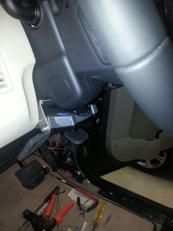
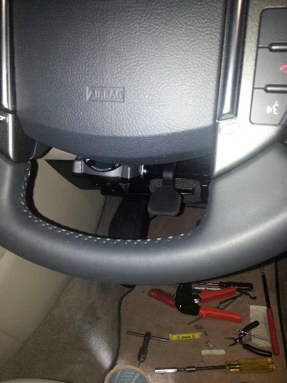
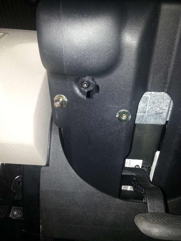
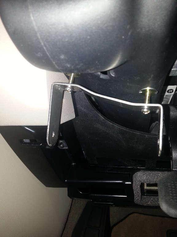
Still in the throws of finishing the EBC install on my MY13 D4, a Tekonsha P2, and have installed it under the steering column on the left hand side of the column adjust lever.
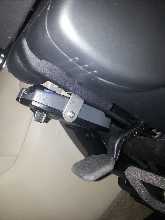
Here are some pic's of the finished install, (next time I will crop them) the upside of this location is that it tucks up quite nicely but you still have easy access to the manual override lever on the bottom and good enough access to the other two controls if you need them.
The down side is you loose most of the steering column vertical adjustment. For me it's not a problem, the column stays where it is anyway, (I am 187cm) but you can balance the loss of vertical movement by locating the controller toward the center of the column. This will require you to reduce the width of the column adjusting lever on the inner edge, but again I do not see it as a significant modification.
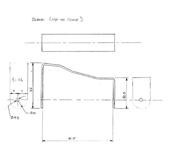
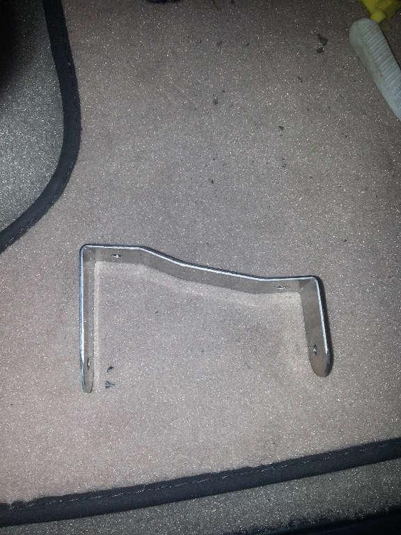
This is the bracket design, or a sketch that I was going to use to model it in CAD, hence it is a bit rough, but the shape is accurate. Like many, a bit time poor so the CAD model is low priority. If you are considering this and want a better image send me an email and I will send it to you or download it from the gallery.
I used 2 expanding wall anchors to provide a positive attachment, you drill 7mm diameter hole, put the anchor in and expand it, you end up with an M4 screw to use for the attachment. There are no issues with clearance to any components inside the steering column cover lower.
I used some 1.6mm stainless that I had sitting around, but mild steel would be fine. I have since painted it black, but unpainted contrasts better in the photo. White marks are chalk lines for location.
Just doing this post was a bit of an education in itself, hope it might be of use.
A couple of final thoughts, on advice from this thread I went looking for 4mm^2 wire (this "^" means raised to the power of) for the brake feed to the rear. It seems auto electricians call it 6mm wire. I actually counted the strands (52) and measured the diameter of the individual strand (0.3mm) and calculated that the cross sectional area of the copper conductor (the important bit) is 3.68mm^2, so, nominally 4mm^2 conductor. I talked to the auto electrician I bought the wire from and they could not actually explain it, but there you go.
Last thing (sorry), I also found a thing called a stud diode to put in the red brake wire, it is physically a lot bigger than a typical 3A diode and makes connection easy and does not reduce your 4mm^2 conductor down to 1.3mm^2 through the diode.
PeterJ
Last edited by WhiteD3; 22nd April 2014 at 04:02 AM.
Reason: Correction made for poster
Just a quick question Peter,
You say the Diode in the Blue wire?
Just wanting to confirm that this is a typo & you haven't installed the Diode in the blue wire as it SHOULD be the RED wire as per install instructions.
I'm having a P2 fitted after Easter. I was also going to get my 7 pin plug removed and a 12 pin plug put back in its place. Is there any reason not to do this? I have a trailer with a 7 pin plug (5wires) but I can get the converter for that I'd welcome everyone's thoughts.
If you live in Australia (and do not intend to tow British trailers), it makes all the sense to install an Australian 12 pin flat socket. Good luck finding a round 12 core cable to fit into the socket though. I bought mine online from UK ...
You might try installing a 7 core and a thick 5 core cable together, however you will probably find that they do not fit into any available 12 pin socket.
Last edited by ken224; 19th April 2014 at 08:24 PM.
Reason: typos
Has been done hundreds of times before & yes a good idea. This way you end up being able to tow 3 types of trailers.
7 Pin Round, 7 Pin Flat & 12 Pin Flat, which covers just about all trailers.
Thanks for the pic. I did plan on swapping out the black right hand plug for the 12 pin and eventually swapping the white one for an Anderson plug. I guess I'll do as per this pic.


 Reply With Quote
 Besides, it is dated 1998 and probably trumped by the said ADR38/03.

")

Bookmarks