
Originally Posted by
Bush65

My opinion hasn't swayed from when I said:
I got the impression that the main reason you thought I was modding the body outrigger was the top plate width, looking at my original pics it was hard to tell that the top, at chassis, is the same width as TA mount. You now know this and have elaborated.
The dynamic load from the trailing arm can and does vary from very high compression (in some circumstances equivalent to the vehicle weight), to fairly high tension. The magnitude of the load fluctuation is the difference between the two extremes, i.e. it is much greater than either the peak compressive or tensile load. It also undergoes an enormous number of load cycles and both of these factors lead to fatigue failure, unless the maximum fluctuation in the stress is below the endurance limit.
I have pointed out the issues of welds where fatigue is involved and attempted to explain how the load was transferred from the TA to the top and bottom flanges of the chassis within the stock TA mount.
Avoiding fatigue is not about adding material, gussets, etc. all over the place like “belts, braces and nappy pins”. It is all about attention to the details that matter, such as minimising the effect of stress raisers, minimising residual stresses, and eliminating defects/flaws where cracks can start. For example the fatigue strength of axles/half shafts can be increased by waisting to the root diameter of the splines.
Loads will always (without exception) take the stiffest route in their general direction. This is where material is used efficiently, where stiffeners play a great role even if they might look insignificant and where stress raisers should be avoided when fatigue is an issue (stress raisers are not an issue with static loads).
In your modified body outrigger design you have added a gusset between the vertical legs to transfer the TA load. The great majority of the TA load must be transferred through this gusset and the plate that you intend to weld underneath. Have a good look (based on pics that I posted before) at how the path of these loads through the gusset and bottom plate. Now compare this with the stock TA mount design.
How many welds can you count across the path of the load in each of these designs?
none on the OEM mount, edit, 1 on the OEM mount if you count the weld were the inner 4mm plate is welded along the lower fold to the 3mm main body:
4 on mine:
#1, the bottom plate to vertical face
#2, the bottom plate to bottom of internal gusset
#3, the gusset to vertical face
#4, the guesset to top plate through slot for welding
One thing I was thinking of doing is using one peice for the gusset and the added internal plate on inside face of vertical leg. This would be 4mm and a simple 90 degree fold. This would reduce 1 of the welds...
The welds connecting the stock mount to the chassis are unavoidable, but their location, direction, length are fit for the purpose.
Welds, even those executed perfectly, reduce fatigue strength. The direction of the weld has a large effect, as I indicated in an earlier post. Defects in welds are not acceptable where fatigue is a concern. Fillet welds are worse than butt welds.
Because you don't have good access to weld both sides of your gusset and bottom plate, you will not be able to make a good weld and prevent defects - backing strips would help, but IMHO the design is flawed and this is what should change.
Internal gusset can be welded both sides. I can fit my MIG gun in there with good angle and this would be welded on bench before fitting to chassis as the gusset is not weled to the chassis rail. The top and bottom of gusset would be welded via a slot cut in top and bottom plate, this would result in a edge to egde weld.
Bottom plate would be fitted last, in postion on chassis. I have looked closely at the bottom plate at RA and front body mount, both of these are only welded on the outside, not internally.
Have you considered access for welding the mounts to the chassis and the difficulty of welding in positions other than downhand?
Yes, as a carpenter I am use to dealing with pysical limitations over those of a simple pen stroke in a design. I have thought all along about the fabrication process and fitting of mount and one of the reasons I have made a full size mock up. I know that vertical down is not considered ideal in structural welding, but have been lead to believe it totally acceptable in welding materials 3mm thick.
The body load on the outrigger is smaller than the TA and always in the same direction, so the load fluctuation is much less than that from the TA.
IMHO it is better to give priority to accommodating the major loads, i.e. TA load in this case. Quite often the design for the major loads will be untroubled by the minor loads or only small changes or tweaks are required. This is why I made the statement at the top of this post. You have done the reverse and exposed your design to considerable difficulties, including fatigue failure, access for welding, and access to the bolts for the TA bush.
My preference would be similar to what Slunnie suggested, using Patrol TA bushes.
I went back and re read Slunnies post, though I was a bit confused when he mentioned not overlaping top and bottom of chassis rail, but then said weld it to the sides, making sure it contacts the top and bottom, plates....now without overlapping, this would mean the corners, which we have already discussed as not being a good idea.
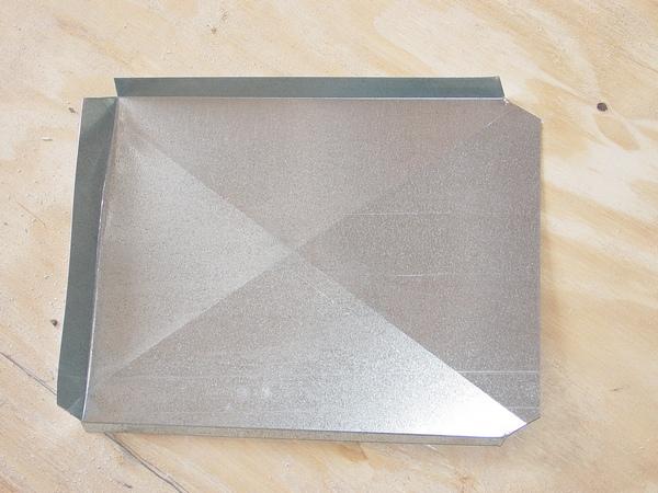
However if I were to stick with the LR TA to chassis bush I have used an old cardboard carton to show how I would base it on the design of the LR mount – see pics below.
Bend the 3 mm thick plate as shown in the pics by the cardboard mock-up against the LR TA mount.
Now take your modified outrigger mock-up which is wider (horizontal direction) where it joins to the chassis rail. The rearward vertical leg stays as is and welds (use virtual welds for cardboard) to the new TA mount. The chassis bush for the TA bolts to this as per your earlier pics. It should also have the same doubler plate.
The forward vertical leg of the outrigger needs to be shaped to fit against the new TA mount – see dashed line in second pic. The TA mount can be trimmed back to leave a stiffener as shown by the solid line in the second pic.
Finally add the proposed bottom plate from end of outrigger to underside of TA mount.
IMHO a better design for the outrigger is to press up 2 'L's instead of a 'C' plus bottom plate. Joining the 'L's together to form the box section involves no more welding but they are simpler to press than a deep 'C' section.
All of you questions pretty much relate to understanding the same issues. Think of it this way: load is carried by the stiffest part.
For example take two coil springs of identical length, but one is soft and the other is stiff. Say the load to compress each spring 1 mm was 1 Newton for the soft spring and 100 Newton for the stiff spring. Now if the springs were arranged one inside the other so that a load compressed both springs simultaneously, by an identical deflection. If the load was 101 Newton you should clearly see that both springs will compress 1 mm and the soft spring will only carry 1 Newton while the stiff spring carries 100 Newton.
If we want to increase the load capacity of a structural member, one way is to add material where the stress is most severe, but we can only achieve the desired result if the material is added where it is sufficiently stiff.
Take roof sheeting. The thin sheet can carry considerable load (compared to flat sheet) because the material is stiffened by the ribs.
Material too distant from a stiffener is not capable of carrying as much load as it can close to a stiffener. The thicker the material the further the distance it can be from the stiffener. Stiffeners can take many forms, such as ribs, webs, flanges, corners in LR chassis rails, pressed lips, virtually anything that constrains the element from flexing (flex is the opposite to stiffness – recall what I said about loads and stiffness) to in thin direction and forces it to remain straight while subjected to the design load.
I'm sure you would have observed when building a roof, that when the trusses are first stood up they can't carry large loads but as purlins are added, the load capacity increases because the purlins keep the top chord of the truss straight. In this case the purlins “stiffen” the chord in the direction in which it was previously able to flex.
Thick steel sections and plates are rolled by a “hot mill” - the steel is red hot while it is rolled.
Sheet and strip is first rolled on the hot mill and further rolling, to produce thinner sheet, or to form it into sections such as hollows (shs, rhs, chs), 'C' or 'Z', etc. is performed in a cold mill (sheet and strip) or in a roll former (a series of rolls where each set of rolls produces an incremental change in the section shape from the flat strip to the finished section).


 Reply With Quote
 I had touble visulaizing the actual end result without it being absolutely booty fab... I never saw any pics and new that I was missing something as Sam is pretty switched on.
 Im struggling with the simple stuff here and I think John may feel like he is dealing with a special needs kid.


 . Alot of good designs require a more complex shape than can be simply folded....then its the turn of many 100's of tonnes press and dies to "stamp" or "form" the part....the LR OEM TA mount is such a part...not just simply folded.
")

Bookmarks