Page 5 of 8 FirstFirst ... 34567 ... LastLast
Results 41 to 50 of 79

Thread: PUMA - Drivetrain Upgrade

  1. #41
    Join Date
    Oct 2010
    Location
    Dixons Creek Victoria
    Posts
    1,533
    Total Downloaded
    0
    Quote Originally Posted by ashtrans View Post
    Hi Wagoo,

    ours are waisted, the diameters are reduced over about 50mm with a big rad at the shaft end of the taper so it's not obvious to the eye but they are waisted exactly for the reasons above, to help get the stress away from the splines and allow them to flex,

    Dave
    Thanks for the reply Dave.As you say,the wasting isn't obvious in the photos, but the better finish and lack of stress risers compared to the originals certainly is.
    Wagoo.

  2. #42
    Join Date
    Aug 2006
    Location
    WA
    Posts
    13,786
    Total Downloaded
    0
    [QUOTE=wagoo;1528910]
    Quote Originally Posted by isuzurover View Post
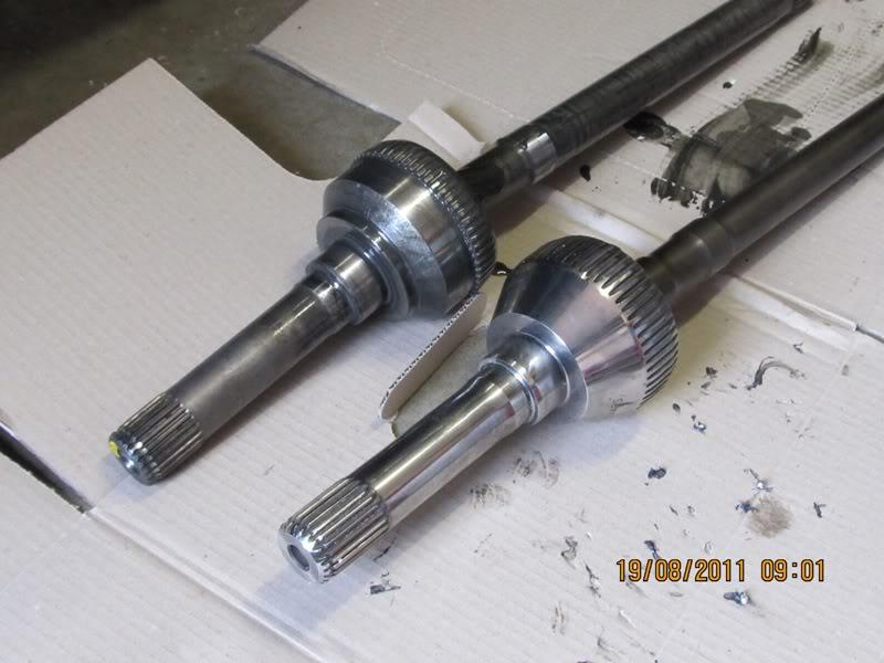
    What evidence do you have that reducing necking down the axles will reduce stress/fatigue in ring and pinions???

    Ben,I can't believe you asked that question.Tell you what. Just between you and me, If you want to delete it, I'll do the same on this reply .
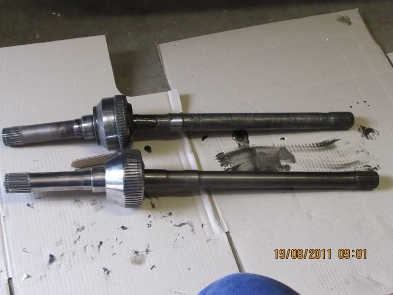
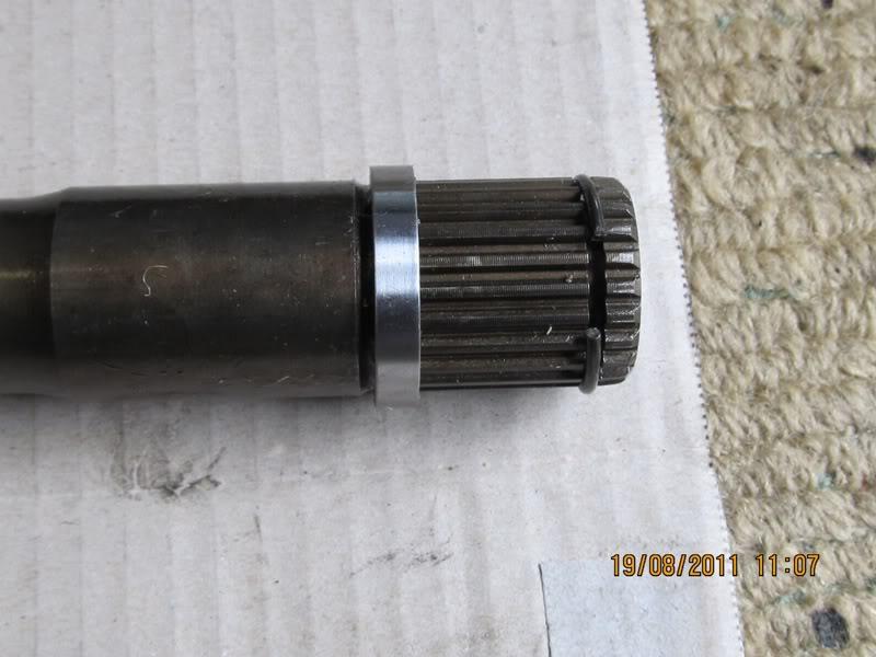
    One doesn't need to be a rocket scientist to work out that a shaft that can flex to absorb shock loadings, such as when a spinning wheel suddenly finds traction, will also reduce the impact shock on the rest of the drive train that is supplying torque to that shaft. It's similar in a way to how the spring loaded slipping clutch on a tractor mounted slasher protects the driveline when the blades strike a hidden rock or tree stump. Or why the flexible torsion bars on my Holden Jackaroo prevent me and the rest of the vehicle from disintegrating when the front wheels strike a bump.
    As I mentioned earlier, the finish on Daves shafts is probably good enough without requiring honing and polishing. After all, the torsion bars on the jackaroo weren't polished and live in an unfriendly environment, and they've flexed millions of times in their 400.000 km lifetime.
    Wagoo.
    Bill - I should have added "in real world LR applications" to the end of that sentence.

    I was trying to say there is no evidence that waisted axles will make any of the other components last longer in a landie - in a measurable real world sense.

    E.g. All the waisting in the world won't stop the crownwheel flexing away from the pinion under drive torque.

  3. #43
    Join Date
    Jan 1970
    Location
    'The Creek' Captain Creek, QLD
    Posts
    3,724
    Total Downloaded
    0
    Quote Originally Posted by isuzurover View Post
    I didn't realise we were talking money-no-object options here

    They were probably gun drilled to save weight as well?

    Bush65 designs such items for a living AFAIK (or used to). I am sure he will be back soon to add more to this.
    Waisting shafts and head bolts etc. that are subject to shock loads will greatly increase their life if done properly.

    This is done to increase the resilience so the energy from shock loads is absorbed by converting it to strain energy in the material.

    Taking as example a typ half shaft, there is a stress raiser at the splines, which limits the static strength. If the shaft is not waisted, the torsional stress in the unwaisted section will be much lower than at the spline section.

    Waisting the shaft so as much of the shaft as possible is stressed to the same level, maximises the resilience and the strain energy that can be created. The stress in the half shaft is not greater than at the splines, but the shock load seen by components, including half shaft, cv's, ring and pinion is reduced by the impact energy absorbed as strain energy in the shaft.

    Details such as stress reducers (e.g. fillets where diameters change) should be used.

  4. #44
    Join Date
    Jan 1970
    Location
    'The Creek' Captain Creek, QLD
    Posts
    3,724
    Total Downloaded
    0
    [QUOTE=isuzurover;1529168]
    Quote Originally Posted by wagoo View Post

    Bill - I should have added "in real world LR applications" to the end of that sentence.

    I was trying to say there is no evidence that waisted axles will make any of the other components last longer in a landie - in a measurable real world sense.

    E.g. All the waisting in the world won't stop the crownwheel flexing away from the pinion under drive torque.
    People can claim that because fatigue life can vary by a lot, particularly because the load spectrum will vary greatly, but it doesn't make it a correct statement.

  5. #45
    Join Date
    Oct 2010
    Location
    Dixons Creek Victoria
    Posts
    1,533
    Total Downloaded
    0
    [QUOTE=isuzurover;1529168]
    Quote Originally Posted by wagoo View Post


    E.g. All the waisting in the world won't stop the crownwheel flexing away from the pinion under drive torque.
    Ben, the crownwheel wouldn't flex away from the pinion if the wheels had no traction. and IMHO it is doubtful that even standard 2 pinion carrier would flex even at maximum tractive effort.I believe it is shock loads that flex the carriers, and either destroy diffs instantlly, or contribute to fatigue that leads to failure even when the diff is subject to relatively light loads. Since shock torque is generally much greater than drive torque, a shock absorbing medium such as a torsionally flexible halfshaft must reduce carrier flex and contribute to longer life.
    Wagoo.

  6. #46
    Join Date
    Apr 2009
    Location
    Central Coast NSW
    Posts
    1,576
    Total Downloaded
    0
    Front End - here we go....

    Wheel and Brake calliper off, 2 x 13mm bolts and release clip on brake line to remove calliper. Factory drive flange removed 5 x 17mm bolts plus one cir clip on the end of the axel.


    Next remove hub, 6 x 17mm bolts


    Hub off, CV joint and axel exposed


    Ensure wheels are straight, then simple pull out.


    The factory CV and Axel compared to the Ashcroft items


    The next 2 photo's are of the end on the axel that fits in to the CV and the CV, the small cir clip must be depressed while pushing the axel into the CV, push until you hear a click and the axel is fitted.


    To convert the PUMA front wheel bearings to oil lubricated you need to replace a grease seal with an oil seal at the back of the disk assembly shown


    Part number shown.


    You also need to remove another oil seal located inside the hub. There is a roller bearing race in front of this seal. Do Not attempt to remove this bearing. Use a screw diver and gentle collapse the oil seal and remove. This will allow the diff oil to migrate along the CV shaft out to the wheel bearings.


    Reverse the process, use loctite as you go and your done.

  7. #47
    Join Date
    Jan 1970
    Location
    'The Creek' Captain Creek, QLD
    Posts
    3,724
    Total Downloaded
    0
    Quote Originally Posted by wagoo View Post
    ... Since shock torque is generally much greater than drive torque, ...
    A suddenly applied load at zero speed will double the static load. In the real world most shock loads also include motion which adds kinetic energy to the doubled load.

  8. #48
    Join Date
    Oct 2010
    Location
    Dixons Creek Victoria
    Posts
    1,533
    Total Downloaded
    0
    Drover, Is there only a single wheel bearing adjusting nut on Deefers now? If so how is it locked in place?
    Just to clarify to avoid possible confusion, the component you called a hub is actually the stub axle or spindle in American terminology. The hub is the component that contains the wheel bearings and the brake disc is bolted to.
    Wagoo..

  9. #49
    Join Date
    Apr 2009
    Location
    Central Coast NSW
    Posts
    1,576
    Total Downloaded
    0
    Quote Originally Posted by wagoo View Post
    Drover, Is there only a single wheel bearing adjusting nut on Deefers now? If so how is it locked in place?
    Just to clarify to avoid possible confusion, the component you called a hub is actually the stub axle or spindle in American terminology. The hub is the component that contains the wheel bearings and the brake disc is bolted to.
    Wagoo..
    Okay cool, hub, spindle - got it....

    Yes, only one giant nut, 2 1/16 or 52mm.

    Locks in place by bending over a rim of thinner metal on the outside of the nut. The "spindle" has a machined flat edge that allows the rim of the nut to push against, once folded over, stopping it from working loose.

    Not sure about adjustments, was told be English Auto service just do it up as tight as you can get it.

    Did it that way, could still turn the "hub" with only slight resistance by hand, so it seemed okay.

    Have done nearly 250k's since Friday and all is well, not even an oil leak since converting from grease to oil lubed bearings - happy days....

  10. #50
    Join Date
    Jan 1970
    Location
    NSW far north coast
    Posts
    17,285
    Total Downloaded
    0
    Quote Originally Posted by wagoo View Post
    Drover, Is there only a single wheel bearing adjusting nut on Deefers now?
    [snip]
    Wagoo..
    Bill, IIRC it's been that way since the TD5 came out.
    I think they use a machined spacer between the two taper rollers so that the pre-load is factory set and you just do the nut up as Drover said.

Page 5 of 8 FirstFirst ... 34567 ... LastLast

Bookmarks

Bookmarks

Posting Permissions

  • You may not post new threads
  • You may not post replies
  • You may not post attachments
  • You may not edit your posts
  •  
Search AULRO.com ONLY!
Search All the Web!