


 Reply With Quote
My flanges look like this , well very similer T/C flange points more twards the sky .

 Wizard
+50mm Front springs are actually 50mm longer that stock springs, but rear +50mm are the same length.
The lift is achieved by a stiffer rate.
In any case the height of rear will have no consequence on the front prop angle. If you think about it the rear height would only pivot the front wheels on the stub axels, not actually affect the front suspension/diff position to the chassis.
The TC case flange, on a PUMA, points to the floor (up), but as the front suspension or lift or travels down, the top of the diff flange travel away from the top of the TC flange, the bottom of each flange travel together.
The CC arms cause the top of the of the diff flange to rotate towards the rear of the vehicle, or causing a better alignment of the two flanges.
The flanges needs to be within 3 degree of being parallel. The height difference is not the major issue. That's why we use a DC joint, but not even the DC joint can compensate of the not being parallel. It causes the centre bearing to over work, over heat and inevitabley it will fail.
(If you decipher that mess that I just wrote....well done)
Cheers
Master
My flanges look like this , well very similer T/C flange points more twards the sky .
Master
Originally Posted by Dockstrada

Maybe it's slightly out of phase? Or is it one of those where that's not applicable?
Wizard
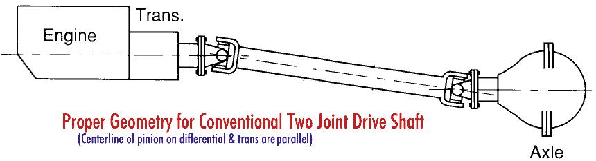
Nice picture, do you have one for a standard shaft ?
I am struggling to understand the role of the DC joint in your picture. With that said, I just looked at mine and it also appears to be per your picture.
My "long winded"explanation is solely based on advice from Cumming Trucks machine shop. Who advised to perform the caster correction for longjebity of the DC shaft, the machine shop manger spoke at length about 3 degree maximum variation in flange angles.
Master
yeah im just thinking outside the square at the moment .
Just checked the angle of the T/C flange using the iphone leveland it was aprox 11 degree diff flange was aprox -3.6 degree and shaft angle was aprox 15.5 degree .
so if anyone can work that out, great . let me know if im in a world of hurt .
Pic as requested .
Master
Ok Il ask ! what's out of phase mean ?
TopicToaster
Dockstrada,
Try this

Wizard
It can occur when the slip joint is pull apart and not put back together in original position misaligning the splines, causing the uni to be out of phase.
Normally the to halves of the shaft will have an indicator on each to align to. Sometimes it is just a painted mark.
YarnMaster
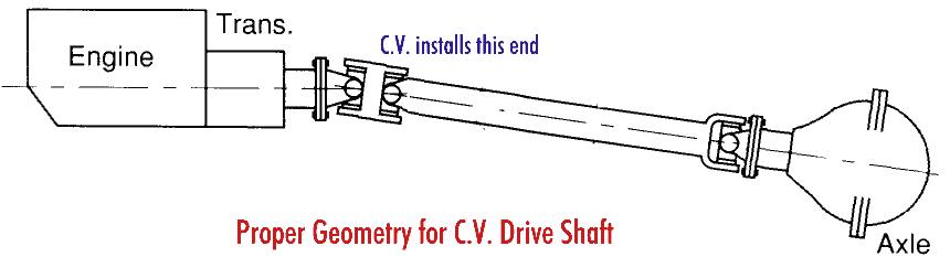
This drawing is correct for when a double cardan joint (also known as constant velocity or CV joint) is used.
The pair of joints in the double cardan joint are forced (by the centre ball) to work at equal angles. Because the angles are equal the angular velocity of the driveshaft is the same as the transfer case output shaft (this is why they are also called constant velocity).
The standard cardan joint at the diff end should only have a small angle change. As stated less than 3 degrees, but less is better. Some people like a slight change so the needle rollers don't stay static.
Only at zero angle will the angular velocity of the diff pinion be equal to the angular velocity. As angle change increases, the angular velocity changes 4 times per revolution. Change in angular velocity = angular acceleration and this is what causes vibration in this case.
The first pic (Tom Woods shaft) and this drawing show the 2nd joint of the double cardan joint and the joint at the diff in phase. This is how it should be.
Wizard
I now assume that this is what o'l mate at Cummings Trucks was referring to. It seems that I have totally misunderstood the whole " 3 degree" thing.
At least I'm on to it now.
 Posting Permissions
| Search AULRO.com ONLY! |
Search All the Web! |
|---|
|
|
|

Bookmarks