Page 8 of 69 FirstFirst ... 6789101858 ... LastLast
Results 71 to 80 of 690

Thread: Meet my 90, and share the adventure.

  1. #71
    Tombie Guest
    I watch your work and the quality of it is without peer.. Exceptional...

    I do wonder if you aren't making it much more complex than it needs to be though!

    However, I can see it may be an exercise in "what can I do"...

    Either way - keep up the quality work!!

  2. #72
    Join Date
    May 2014
    Location
    Tamworth NSW
    Posts
    4,295
    Total Downloaded
    0
    Quote Originally Posted by Tombie View Post
    I watch your work and the quality of it is without peer.. Exceptional...

    I do wonder if you aren't making it much more complex than it needs to be though!

    However, I can see it may be an exercise in "what can I do"...

    Either way - keep up the quality work!!
    Cheers Tombie!

    I've been thinking a lot of what my goal is with this vehicle. It's a tricky philosophy to ponder when we are dealing with a vehicle which on face value is rather primal. On one hand I'd love to just go gung-ho with tek screws, zip ties and get it all fitted out over a weekend... which wouldn't look out of place amongst all the rivets and spot welds, but on the other hand, I want to have something that has been designed with thought, educated decisions, and foresight.

    It's easy to just throw money at a car and buy the first thing everyone recommends (people do this every day of the week at big box 4x4 stores- and admittedly get some very nice vehicles out the other end), but playing devils advocate and looking at the whole design and building to a standard or a performance goal is usually way more insightful- both in the end outcome, and from a personal learning experience too. I'm guaranteed to make mistakes (and will probably post my failures here too!), but it's all part of the 'adventure'- hence the title of the thread. It's not a build thread, not a tech thread, not always defender specific, but an eclectic orgy of ideas that come together in a weird yet beautiful way

    I really enjoy drawing inspiration and ideas from other industries and using high quality solutions in 'off license' ways to meet a desired outcome. For example, the winch cables are planned to be secured with Stauff clamps - normally used in piped industrial gas installations to secure poly or stainless pipes. They wouldn't be out of place on a multi billion dollar air separation unit, or as a fixture for a retciulated oxy/DA system at a TAFE or engineering workshop.

    The balance between complex solutions and the problem at hand is a fine line to walk. If you know the desired outcome, you can find many ways to get there. Some paths are better than others, some are simpler, more complicated, or more reliable. I guess 'engineered reliability' is what I'm going for. I'm not an engineer (I don't have a train, or that piece of paper), but willing to give my ideas and goals a red hot go and learn something new along the way.
    -Mitch
    'El Burro' 2012 Defender 90.

  3. #73
    Tombie Guest
    Keep it up! Its a pleasure to watch the detail you are putting into the build..

    Really like the Stauff clamps - were used in what I did for a long time... Even have some holding some gear in my workshop...

    I'm enjoying the 'out of the box' methodology you are applying - shows great planning and execution and attention to detail...

    Just one question...

    Where do you find the time? I still have a task list about 40 lines long!

  4. #74
    Join Date
    May 2014
    Location
    Tamworth NSW
    Posts
    4,295
    Total Downloaded
    0
    Quote Originally Posted by Tombie View Post

    Where do you find the time? I still have a task list about 40 lines long!
    I have a very patient partner...
    ...and my to do list is growing longer every day
    -Mitch
    'El Burro' 2012 Defender 90.

  5. #75
    Join Date
    May 2014
    Location
    Tamworth NSW
    Posts
    4,295
    Total Downloaded
    0

    More Build philosophy

    Probably not the most interesting topic to pen today, but what the heck. I find it interesting, and you mob will just have to deal with it.


    All the electrical projects I've done to date have sort of had a goal of making things fairly contained, reliable and safe. A premium was put into things like protection from water ingress, dust and vibration to ensure that the finished product won't be at the mercy of the elements. Likewise I've resisted hacking holes and brackets into the vehicle wherever possible, utilizing the space and features of the vehicle wherever I can. I guess all my years working on jap imports with cramped, tiny engine bays and no space to work with came as a shock to the system, and I've been subconsciously trying to build a cramped little car ever since

    I have been reading and pondering this article concerning the wiring of automotive electric systems and accessories. I'm finding it really interesting. I'd recommend anyone who is that way inclined to have a browse over it and pick the eyeballs out of it... a lot of it is on the theoretical side of things, but the guy appears* to know what he's talking about.

    Of particular interest is the debate between wiring high current loads direct to the battery or direct to the chassis earth point. There are some interesting points relating to the cross sectional area of the chassis, body panels relative to the negative cable coming off the accessory (ie many times larger CSA). There are also considerations as to the likelihood of the load failing and creating voltage spokes which can damage other vehicle systems, or creating electrical noise for other engine systems, sensors etc. Wiring considerations for voltage drop or resistance to heat is another interesting topic covered.

    The topic of earthing a winch (amongst other accessories) seems to be one of those can of worms debates. I'm hoping that wiring the winch direct to the accessory battery positive and negative is the right way. Warn (and other winch manufacturers) recommends this, but probably making the assumption that no other upgrades will occur to make a chassis earth viable. I could have saved quite a bit of money on cable if I'd only upgraded the 30cm long battery negative to chassis cable rather than the whole 9 yards

    I guess once any potential failures are put aside, having a dedicated circuit for a high current load is not a bad thing. Open to thoughts about this.


    * as much as an anonymous author on the internet can be trusted, I guess...
    -Mitch
    'El Burro' 2012 Defender 90.

  6. #76
    Join Date
    May 2014
    Location
    Tamworth NSW
    Posts
    4,295
    Total Downloaded
    0
    I put the feelers out on this thread regarding terminal spacing on the Devon 4x4 battery tray when using the optima D34M batteries.
    I sourced these thru Michael (user rrturboD on AULRO). Ordered Monday, arrived Wednesday, stellar turnaround time for a regional area like Tamworth, and great service to boot- thanks mate!

    I've done a preliminary install to get the measurements to put any future questions about the suitability of these batteries in the knowledge bank for future users who might be interested.


    Optima D34M batteries in Devon 4x4 tray (for 2007+ defenders)
    The D34M (BCI group 34) Batteries are HALF the length of a stock defender puma battery. Two BCI group 34 batteries fit side by side in the tray.
    The D34M batteries are Left hand positive, and this will allow the + terminals to be fit in the centremost section of the battery box, with the negative terminals under the seat box panel closest the door, and under the passenger (LHS) seat rail.

    The batteries fit with 14mm clearance along the side of the battery tray (when installed in the vehicle, pictured), and have approx 3mm clearance front to back. I will probably use a piece of wood to prevent undue movement once it's all setup for service (and not on my living room floor AKA ghetto workshop)


    The left/right side clearance (14mm) allows the batteries to be spaced towards one terminal or the other, which is the main orientation that will effect the spacing of the battery tie down clamp and any accessories you wish to wire to the 5/16" post terminals on the battery. The pics show how I've aligned the battery clamp (and batteries within the tray, closest to the negative terminals on the battery.


    In this orientation, the positive crimp lug cannot make contact with the hold down clamp, however the earth will. Being coated copper lugs, the weight of the cable will bend these over time. Insulation of the battery hold down clamp would be ideal, as others have suggested.


    If the lugs are orientated parallel to the clamp, you can bank on about 10mm clearance from the clamp to the outside of the lug. This increases to 16mm if you space it towards the negative as I have.


    I've got a mega fuse holder on it's way, so once that's all done and dusted, the install proper can begin, time permitting.
    Interestingly, the fuse holders I've been looking at are all rated to a max 300A, and the factory Mega fuse is 500A (it's got a nifty Ford logo on it!). Hoping that the starter motor (or anything else in the vehicle's facrtory electronics for that matter) will not draw more than that for long enough to blow the fuse...
    It's also interesting as there could very well be some additional capacity in the fuse (and I'd hope, wiring) to support the dealer fit winch which is connected direct to the starter motor. Again, this is another point of contention for winch installations too.
    Attached Images Attached Images
    -Mitch
    'El Burro' 2012 Defender 90.

  7. #77
    Join Date
    Oct 2014
    Location
    Fremantle
    Posts
    189
    Total Downloaded
    0
    I kept my standard battery ( new design piranha tray) and used a yellow top optima, the only fitting issue was the height, had to play with spacers on the terminals of the aux battery to make sure it fit under the sliding metal cover when the cables were connected, lined it with rubber to be safe.
    Something to check if you haven't allready.
    The battery box top isn't flat on top so it's lower at the end towards the front of vehicle than other end if that makes sense.

  8. #78
    Join Date
    Sep 2010
    Location
    Perth WA
    Posts
    1,423
    Total Downloaded
    0
    Quote Originally Posted by Toxic_Avenger View Post
    I've got a mega fuse holder on it's way, so once that's all done and dusted, the install proper can begin, time permitting.
    Interestingly, the fuse holders I've been looking at are all rated to a max 300A, and the factory Mega fuse is 500A (it's got a nifty Ford logo on it!). Hoping that the starter motor (or anything else in the vehicle's facrtory electronics for that matter) will not draw more than that for long enough to blow the fuse...
    It's also interesting as there could very well be some additional capacity in the fuse (and I'd hope, wiring) to support the dealer fit winch which is connected direct to the starter motor. Again, this is another point of contention for winch installations too.
    You can get a 500Amp megafuse holder to fit the original fuse from Jaycar. It was the only one we could find when we were doing ours.

  9. #79
    Join Date
    May 2014
    Location
    Tamworth NSW
    Posts
    4,295
    Total Downloaded
    0
    Part 1
    I'm trying this new AULRO picture attachment doo-dad, as chances are all the stuff here will fall off the internet one day when the Imgur images are no longer hosted. Going to upload in a few parts so that there are posts with a number of images each.


    I managed to score some time on the Landy today, kickin' ass and takin' names. I make this look easy

    Spent Saturday doing some detailing on the other car. Came up alright for a 24 year old datsun Doing a wedding with it next weekend, so thought it was a good opportunity to give my fairlady its yearly polish


    Back to the battery setup, which is probably why most of you are putting up with this thread...

    Ordered one of these last week, which should land on my office desk early this week:

    It's the Blue Sea Systems 7721 Mega fuse holder. Nice bit of gear, ignition protected, so should have no issues with flammable battery gases venting if it ever comes to that 
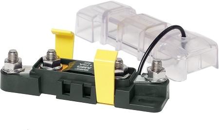
Plus, being a mega fuse holder, the existing fuse will slip right in, and do all the things a good fuse should- sit there and look pretty, not blow, etc.

    This purchase will allow me to get rid of the abortion of a fuse holder than Land Rover decided to attach to this vehicle:

    It will be a good day when I can get rid of that. Seriously, who ever thought that the stock positive terminal / fuse holder with its cone style clamp arrangement was a good idea? It seemed that no matter how hard I wrenched on that nut, it was still loose on the battery terminal. RIP.

    This is what I had to deal with to begin with. Note the complete mind**** of wires which is an accumulation of driving lights, LED's, UHF, air compressor (I'm guilty of that, it was a temporary install ) plus all the stock wiring.


    After locking then unlocking the car, and quickly disconnecting the vehicle's battery (to prevent any immobilizer issues) I was able to begin the tear down of the setup.
    First step was to remove the plastic battery box cover under the vehicle (4x 10mm bolts), and then undo the fasteners holding the stock battery tray into the vehicle. I also needed to remove the wheel chock, bottle jack, and tool roll as well. With this out of the way (and a good clean up to-boot) this is what's left of the box:

    And the view back towards the PS door:


    I took the time to drill out the rivets holding in the bottle jack bracket - this will go into the 'stuff I've removed from the defender' box I have. I also removed the metal hooks which sit on the front side of the battery box... I'm not actually sure what they are for, but this too was prime real estate for the parts I have planned to install...
    -Mitch
    'El Burro' 2012 Defender 90.

  10. #80
    Join Date
    May 2014
    Location
    Tamworth NSW
    Posts
    4,295
    Total Downloaded
    0
    Part 2- the tray and re-routing wires

    The test fit of the battery tray went that well, that I bolted it right in! The devon 4x4 tray is a stout bit of gear, fits tight in all the right places, and it leaves plenty of room around and UNDER the tray to route wiring and battery control gear if needed.

    Here is after the cables have been re-routed, but before the batteries are in:


    My idea was to have all the batteries control and winch switching gear within the battery box. Looking at it all mocked up, there is a heap of room to make this happen.
    Things I plan to stack in here are:
    1. Automamtic charging relay
    2. Remote Battery Switch
    3. Mega fuse holder
    4. Type T fuse holder
    5. Cabling as required
    6. Any other junk I can fit in there (jack, tools etc)


    Moving cables around
    There are 3 main cables coming into/out of the box from factory-
    1. The main positive cable that goes to the starter (this is fused at 500A),
    2. the Main positive feed to the main fuse box (which is normally under the driver's seat, but I've got mine in the ex box),
    3. and the main negative cable, which exits the battery box, and grounds to the passenger side chassis rail, and then to the gearbox.

    The engine would be earthed to the chassis, as well as the body panels also (I've noticed there is an earth strap between the firewall and chassis near the driver's side front wheel).


    I have chosen to move the location of 2 of these cables (items 2 and 3), to make the finished wiring a bit neater and more accessible with the new battery position.
    2) Negative (earth) cable:
    This was pulled back thru the grommet it came thru on the rear inboard hole in the battery box, and was threaded back into a hole further towards the front of the vehicle. This required the chassis mounting point to be rotated clockwise 90 degrees - which also allows much more reach on this cable. If all goes to plan, I will not need to remake this to put a 'proper' battery clamp on it (see previous post).
    Pic below shows it's final route (pic is from under car, looking up - the silver component is part of the gearbox mount).


    3) Positive feed to main fuse box
    The main fuse panel under the driver's seat has a lug end which screws directly into the board. The factory path is out of the driver's seat box, up and over the gearbox, and into the passenger seat box thru a grommet. I had excess length on this cable when I relocated the fuse block into the ex box, so I had the opportunity to re-route this to a more suitable location- being the front side of the seat box, alongside the positive cable to the starter motor. I chucked a teeny tiny M4 nutsert into a weird little bracket that was unused, and hooked this wire up and out of harms way with a P clamp. Solid.

    You can see the original wiring location in my previous post.


    I was mildly concerned with the distances to the battery box lid. Going over it now, there is plenty of room. The Positive threaded stud of the battery is 35mm from the battery box lid (represented by my straight edge AKA hi lift jack handle). The negative sits higher at approx 25mm.
    Attached Images Attached Images
    -Mitch
    'El Burro' 2012 Defender 90.

Page 8 of 69 FirstFirst ... 6789101858 ... LastLast

Bookmarks

Bookmarks

Posting Permissions

  • You may not post new threads
  • You may not post replies
  • You may not post attachments
  • You may not edit your posts
  •  
Search AULRO.com ONLY!
Search All the Web!