Page 9 of 69 FirstFirst ... 78910111959 ... LastLast
Results 81 to 90 of 690

Thread: Meet my 90, and share the adventure.

  1. #81
    Join Date
    May 2014
    Location
    Tamworth NSW
    Posts
    4,295
    Total Downloaded
    0
    Part 3 the fit before wiring

    Although I'm still waiting on some other bits to finish the install, it's all coming along well, and I've been able to map out and partially fit some of the bits.


    I was considering putting the ACR on the transmission tunnel side of the box, but when I was able to eyeball it with the battery tray in situ, it was ditch in favour of this:


    This orientation will allow the RBS to feed straight into the winch fuse, then the wiring will turn up, and leave the box thru some cable glands, and carry on over the gearbox to the RHS chassis rail.

    Fuse wise, the plan so far is to have the Mega fuse holder on the front side of the box, closest to the main battery, and the starter / fuse factory box wiring which I have re-routed.
    The T Type fuse is ideally for the winch, but the max amperage they make these at is 400A in a 'fast blow' style... I'm thinking I'll temporarily see how this setup goes, and if it's not working (ie I blow the fuse during normal use), I'll wire direct to the RBS and have the winch un fused. I've got plenty of capacity in the cables I've used, so they can be the fuse

    I'm going to link the charging relay and the RBS together with a link bus- basically joining the RBS (winch switch) and the 2 batteries together, instead of running the winch directly to the Battery and having an additional cable between the battery and RBS input (electrically, I'm not sure if it's best to wire one way or the other...?).

    The front most battery location on the inside (trans tunnel) section of the battery box needs to remain relatively clear of stuff, as this is the clearance area for sliding the battery inward before I can lift it out of the box. Even as it stands there is heaps of room behind the batteries (on the door side of the battery box, so there is lots of room for other projects in the future. Watch this space!

    That's about all for tonight, there should be some more posts thru the week as I progress.
    Attached Images Attached Images
    -Mitch
    'El Burro' 2012 Defender 90.

  2. #82
    Join Date
    May 2014
    Location
    Tamworth NSW
    Posts
    4,295
    Total Downloaded
    0
    More progress was made thru the week on the cabling, I was able to snatch a hour or so of an afternoon before it got too dark outside. Bring on daylight savings!

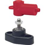
    The fuse holder arrived, and I also took delivery of a link bus bar for joining the RBS and ACR. I procured more 50mm2 cable (using Cigweld superflex for this) and some suitable cable lugs and thick glue lined heat shrink in black and red. I also bought some Projecta battery terminals with the 5/16" threaded bolts to which I'll attach my cables once complete.


    The first cable was the negative link which will sit between both batteries. As this area is under the seat box, height is not as much of an issue and the assembly was fairly straight forward. The terminals were approx 173mm apart, so with a bit of measurement and holding the tongue the right way, I knocked that cable together. As the welding cable was orange, I gave it a sheath of black, and provided some cable strain relief around the lug with the black glue lined heatshrink. This will aslo serve as a good protection from the elements, and oxidation of the copper down the track which can lead to increased resistance.

    With the fuse holder in place, I measured up the main positive feed to the fuse block. This is an odd shaped cable, as it needs to exit the bottom of the fuse block, wrap around the battery, and approach the cranking battery at a nice angle, while maintaining plenty of working room in the battery box for other stuff.
    I repurposed the black plastic cable saddle which was used on the negative cable to train the positive cable into (as close to) a 90 degree bend. More glue lined heat shrink helps to set the bend, and keep the cable path fairly tight to the batteries. The above pic does not really offer any view of how it fits together, but the below pic should:


    ...and fuse holder with cover on:


    For anyone interested, the earth lead on the factory setup is a 50mm2 cable, but it's got this horrendous hard plastic sheath which makes it almost impossible to get anything tighter than a 150mm diameter bend in it. I lopped the factory terminal arrangement off with extreme prejudice. I think it's clear already how much I hated that arrangement. It's now replaced with a 50mm2 lug, and 8mm diameter hole to match the battery post.


    Depending on motivation levels, I might actually relocate this earth cable thru a cable gland lower to the bottom of the battery box, and re-make it with a better cable. Only issue is my ability to crimp a lug in the middle of the cable, as it needs to earth to chassis then the gearbox. This will of course necessitate the sealing of all the holes I now have in the battery box. The path of dynamat in there is getting ever more tempting! It will also help to deaden the large clunk noise that the RBS and ACR will make as they actuate- the rear of the battery box is essentially a drum skin.

    The ACR and RBS are bolted in temporarily, there is a hole behind the RBS which I need to plug (this is where the negative cable originally came thru). I've used stainless hardware here, 5mm hex head cap bolts and nylock nuts. I'd prefer if they never came loose and shorted out on anything. That would be rather embarrassing.


    Still deciding which position the ACR and RBS should be. The ACR needs a cable to go to each battery, which may be an interesting one to route. Likewise, the RBS needs to feed to a fuse block and then to the winch (and go over the top of the gearbox). Each way has it's own advantages, and I'll probably go for the way that looks nicest, and has best utilization of the space at hand.
    Attached Images Attached Images
    -Mitch
    'El Burro' 2012 Defender 90.

  3. #83
    Join Date
    Oct 2014
    Location
    Perth W.A
    Posts
    466
    Total Downloaded
    0
    Checkerpate is SO useful too!

  4. #84
    Join Date
    May 2014
    Location
    Tamworth NSW
    Posts
    4,295
    Total Downloaded
    0
    Quote Originally Posted by YOLO110 View Post
    Checkerpate is SO useful too!
    Yes it is!
    It's like the work bench I don't have. Most of my work is done on the dining room table or in the car port. The footwell of the landy is currently piled high with tools and crap that I use for the task at hand. One night thru the week I spent a whole 3 minutes searching for my 4mm allen key in the fading afternoon light before giving up and finishing for the afternoon. Sure enough, the next afternoon I found that it was right in front of me the whole time.
    -Mitch
    'El Burro' 2012 Defender 90.

  5. #85
    Join Date
    Oct 2014
    Location
    Perth W.A
    Posts
    466
    Total Downloaded
    0
    The MOST bizarre feeling I have ever had was...

    ... 2 hours after I had taken delivery of my brand new Indus silver Defender 100, I was poised over the front wings, blatantly drilling many holes into the body-work of a $50k+ vehicle!!! NUTS

    Looked good after I had the checker plate fitted however!

  6. #86
    Join Date
    Oct 2014
    Location
    Perth W.A
    Posts
    466
    Total Downloaded
    0
    Quote Originally Posted by YOLO110 View Post
    The MOST bizarre feeling I have ever had was...

    ... 2 hours after I had taken delivery of my brand new Indus silver Defender 100, I was poised over the front wings, blatantly drilling many holes into the body-work of a $50k+ vehicle!!! NUTS

    Looked good after I had the checker plate fitted however!
    P.S... NOT doing this on my Keswick 90!

  7. #87
    Join Date
    May 2014
    Location
    Tamworth NSW
    Posts
    4,295
    Total Downloaded
    0
    The first hole is the hardest. I cringed when I installed my air compressor. Now I don't think twice!
    -Mitch
    'El Burro' 2012 Defender 90.

  8. #88
    Join Date
    May 2014
    Location
    Tamworth NSW
    Posts
    4,295
    Total Downloaded
    0

    Layin' a cable (or two)

    Well guys, this saga is coming to an end.

    Over the weekend I ran the cables from the winch solenoid which lives in the driver's side wing, to the battery box.

    The tasks at hand included working out the cable run, make necessary bracket / anchor points and making the final lug crimps and heat shrinking. I also used cable split tube, wrapped in electrical tape, and foil tape where the cables come into areas where there is heat from things like the gearbox, exhaust, cat converter etc.

    The cable
    I've used 70mm2 Cigweld Superflex welding cable. Aside from being a multi strand cable of 70mm2 Cross sectional area, it's also designed for welding applications - if it can survive a jobsite with a boilermaker, it can survive under a landy. This cable is dual insulated, and rated to withstand 655A @ 30% duty cycle, which in welding is generally calculated at 40 celsuis, over a 10 minute welding window (ie 3 minutes operating, 7 minutes rest (out of ten minutes) at 655A. Given the cable run, voltage drop should be <1 Volt under most operating conditions. Also, I get it at a good price thru work which helps
    I don't have a final count of the cable length used, but I'll count the scraps when I'm done, and subtract from the purchased length.

    The cable path
    I've mounted the solenoids under the DS wing. I've got 4x 50mm2 cables run from the winch motor, under the DS headlight, and up over the wheel arch. From there, 4 wires have a junction- 3 attach to the solenoid box, 1- the negative attaches to a terminal post that will bolt to the wheel arch. Going back to the battery box is a positive and negative cable of 70mm2.
    The path goes:
    down DS wheel arch>outside of body support bracket> on top of DS chassis rail> along rail to diesel hose bracket > up to body bracket on underside of body shell > across to PS side of vehicle. From here the cables split- the negative enters the battery box from the rear. The positive enters from the front inside of the battery box (and is secured on the other diesel hose bracket).

    Less talking moar pics

    Used the glue lined heat shrink for the terminals, then butted up the tubing to the end.


    I taped the tubing to the cable with heat shrink on the end, then added an additional layer of heat shrink over the cable to tie it all togher. The negative is shown below.


    Finished the ends... Now is the part where I'd just finsihed wrapping the tubing in electrical tape for literally an hour. Looks good though.


    At the joins which were being made, I used the same 3M Super 33 tape I used for previous wiring in the ex box. It's quality stuff. If you are a connoisseur of fine tape like I am, do yourself a favour and get a roll. Your life will be changed forever. Sticks like excrement to your wife's favourite duvet, and is incredibly heat resistant. The inadvertant blast of the MAPP gas torch I was using to heat shrink the tubing didn't even touch it.


    In the areas which were close to the exhaust, or passing above the transfer case, I opted to wrap the cable/conduit loom with HVAC foil tape. This stuff is equally cool, and should cut cable temps and reduce a lot of the radiant heat in these areas- like factory.

    Just like rollin' a fat one
    Attached Images Attached Images
    -Mitch
    'El Burro' 2012 Defender 90.

  9. #89
    Join Date
    May 2014
    Location
    Tamworth NSW
    Posts
    4,295
    Total Downloaded
    0
    ...After the cables were made I commenced mounting them under the vehicle.


    I was going to use stauff clamps... but I ended up using Narva P clamps in the 19mm ID variety. Readily available, cheap, and easy to work with. The P clamps are sufficient to restrain the cables, and are also relatively space efficient. There is not much room under there to work with, so it was probably for the best. If I were game to weld the chassis, or drill my own new holes to mount the cables, It would be an ideal solution, but alas, I'm just one bloke and a shed, and a project which is over time and budget, but theoretically bulletproof. P-Clamps will do for now

    I used M6 rivnuts, inserted into a 9mm hole. Below is the bracket which attached the drivers side footwell floor pan to the RHS chassis rail. The dingleberry part is a mount for the wheel arch plastic (its plastic on a puma, I think older models were steel?)


    This bracket was also modified with a rivnut. In the below pic, we are looking at the RHS chassis rail, just below the driver's seat. The bracket is there to carry the diesel hoses from the fuel filter, up and over the T case, and to the other side of the vehicle. There is a similar bracket on the other side... seen below:


    Once all was said and done, the cables were secured.
    Below is the first bracket. This is in the driver's side wheel well.


    I'll look into making up a bracket to mount here to keep the crud off the cables. A few bends in alloy should do the trick. Might be a good time to try my hand at AC TIG again... this could get interesting...
    Attached Images Attached Images
    -Mitch
    'El Burro' 2012 Defender 90.

  10. #90
    Join Date
    May 2014
    Location
    Tamworth NSW
    Posts
    4,295
    Total Downloaded
    0
    Back up at the solenoid box, the negative cable is secured with a P clamp to the wheel arch liner, and the positive is cable tied to it. this should stop any interference with the cabled with the air hose.

    The loose end will sit on top of a terminal post. I sort of ****ed up and forgot the winch solenoid wiring diagram... I assumed that the winch motor ground was one of the 3 wires which hooked into the solenoid box directly. I've run another cable, but didn't have enough length to run it the whole way... hence it needs to come up to the terminal post like this:


    Here we are looking up at the RHS chassis rail, and the point at which the cable cross over from the chassis to the body panel. Again more P clamps, and the start of the foil tape as it crosses over the T case.


    Here we see the other side of the T case, and the LHS chassis rail.

    The Left cable is the negative cable, and runs along the rear of the batery box, and enters thru a cable gland. The other wire is the positive, and attaches to the LHS bracket which has the diesel hoses on in... again, another P clamp and a Riv Nut. This was a tricky one to secure, as it is tight quarters up there. I was able to luckily get the bolt started in the riv nut when it was off the chassis, then bolt it into place and tighten it the rest of the way.
    Attached Images Attached Images
    -Mitch
    'El Burro' 2012 Defender 90.

Page 9 of 69 FirstFirst ... 78910111959 ... LastLast

Bookmarks

Bookmarks

Posting Permissions

  • You may not post new threads
  • You may not post replies
  • You may not post attachments
  • You may not edit your posts
  •  
Search AULRO.com ONLY!
Search All the Web!