
Originally Posted by
Toxic_Avenger

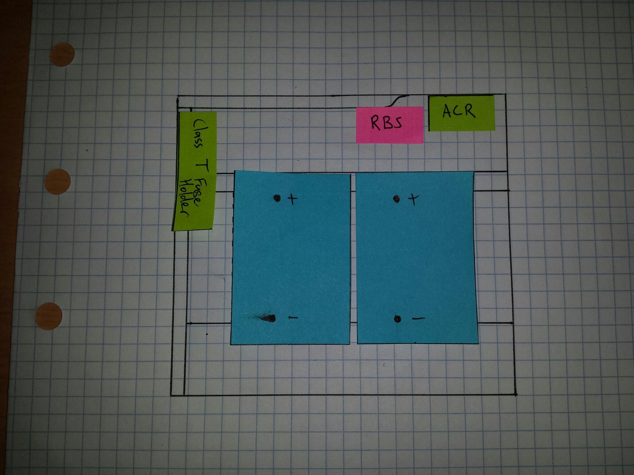
I'm hoping to fit 2x group 34 size batteries in the battery box, along with a class T fuse holder for the winch, a Remote Battery Switch, and an Automatic Charging Relay. It's going to be a tight fit, so I spent some time with the tape measure and a notepad, and got to work. I'm no Picasso, but it made sense to me at the time.
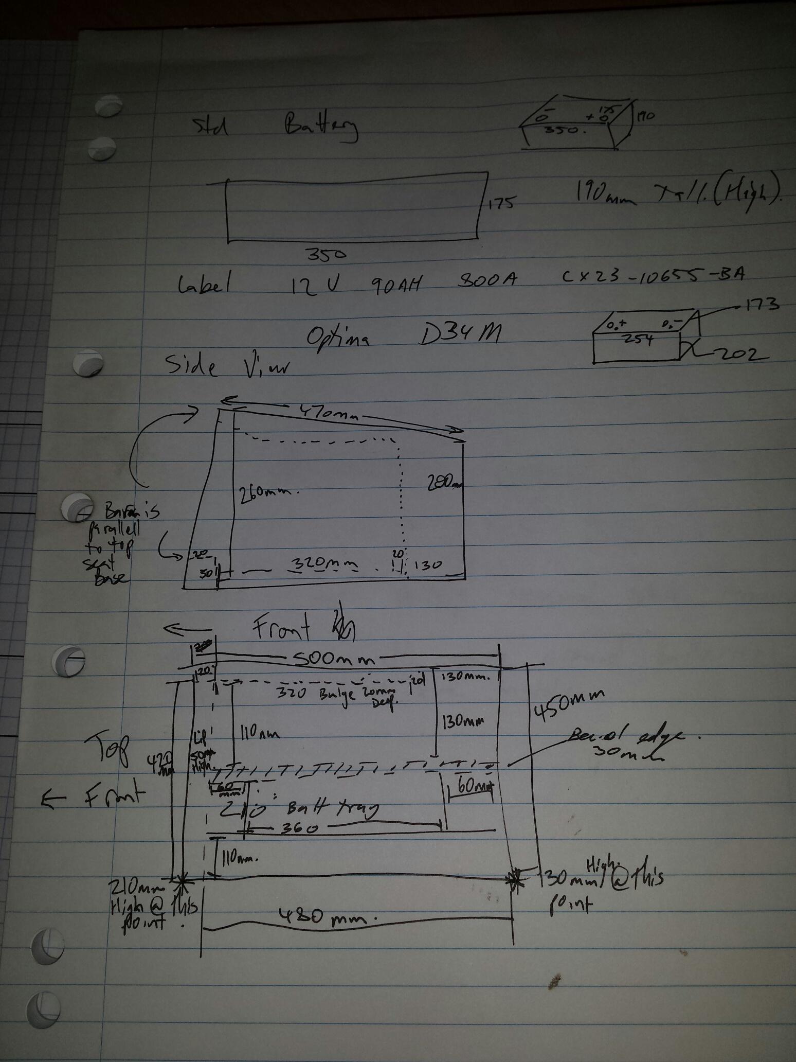
Anyone that's looked at the defender battery box knows it's a weird shape. the base is flat (relative to the chassis). The front face which adjoins the footwell is raked back, and the top section, which the seats affix to, falls aft (or was that daft?...).
Inside, the body panels are no better. The panel which adjoins the transmission tunnel has a bulging section which pinches in towards the rear of the vehicle. The front of the cavity has a spot welded box section for strengthening. the base is on LSD- flat closest to the trans tunnel, a depressed section where the factory behemoth of a battery lives, and a angled surface closest to the door which takes up a fair bit of space (but presumably is there to allow it to clear the chassis).
Needless to say, I've decided to forego designing something myself to fit batteries into such hostile terrain.
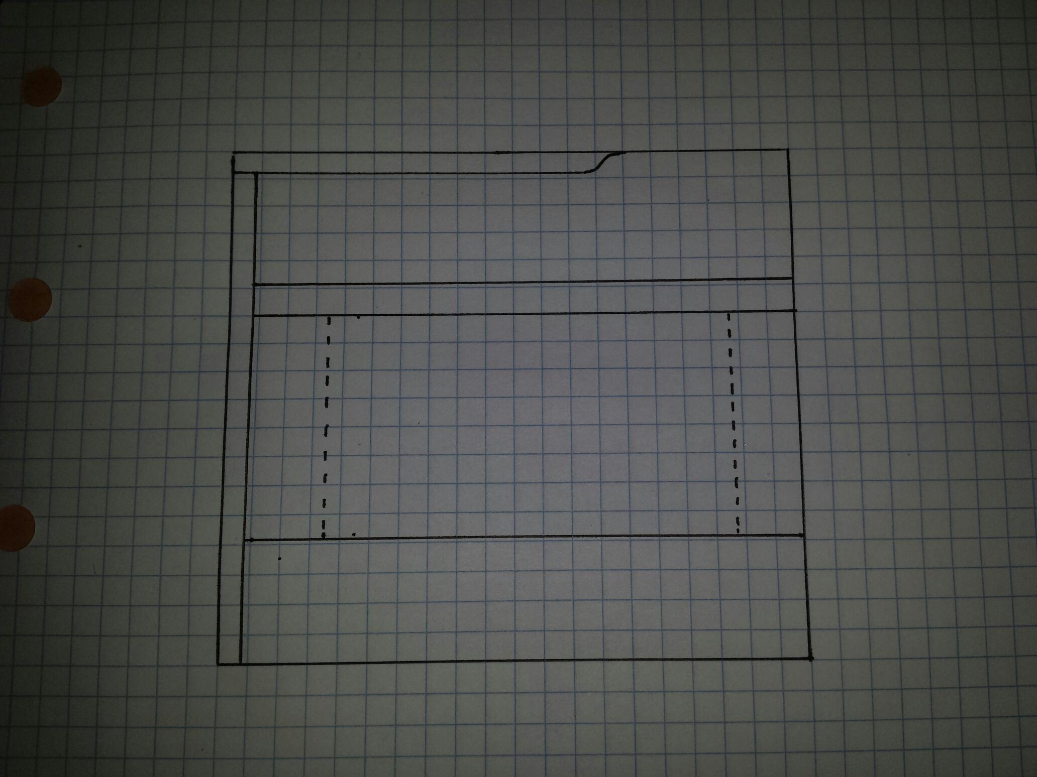
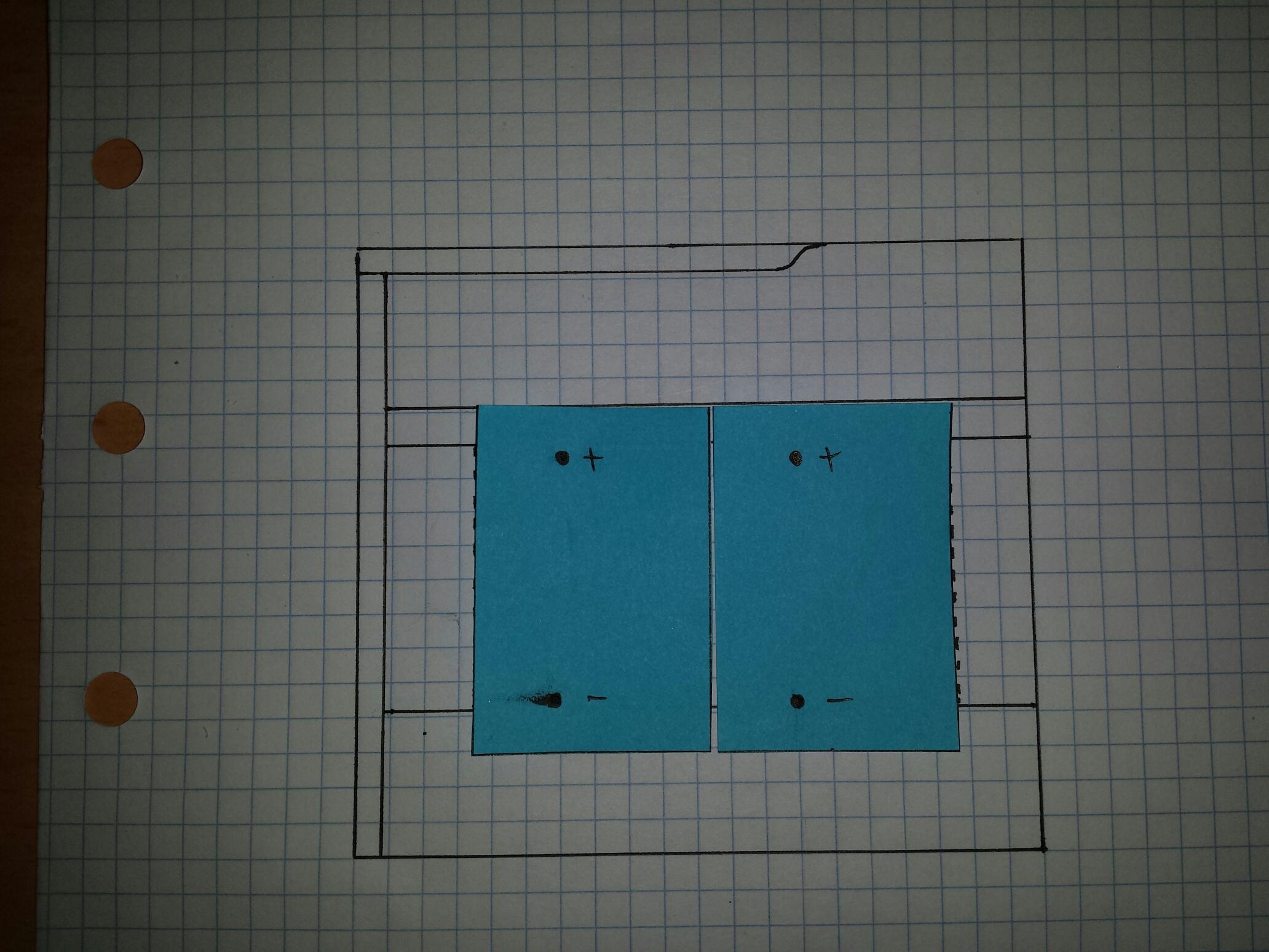
Once I got back to the comfort of the study, I drew a scaled Plan view image of the battery box, to see how I could Tetris everything together. Tetris is not a verb, but it is a fitting one in this instance. Each 5mm square on paper is 25mm in the battery box.
The battery of choice is a BCI Group 34 unit - namely a optima D34M - a dual purpose AGM battery with 750 CCA, and 55Ah. Terminals in this setup are both SAE posts, and 5/16" threaded stainless studs.
This leads to the next item in the puzzle- scaled post-it note batteries.
Interestingly, 2 optimas side by side are approx the same length as the stock battery (stock battery tray is denoted by the dotted line in the plan).
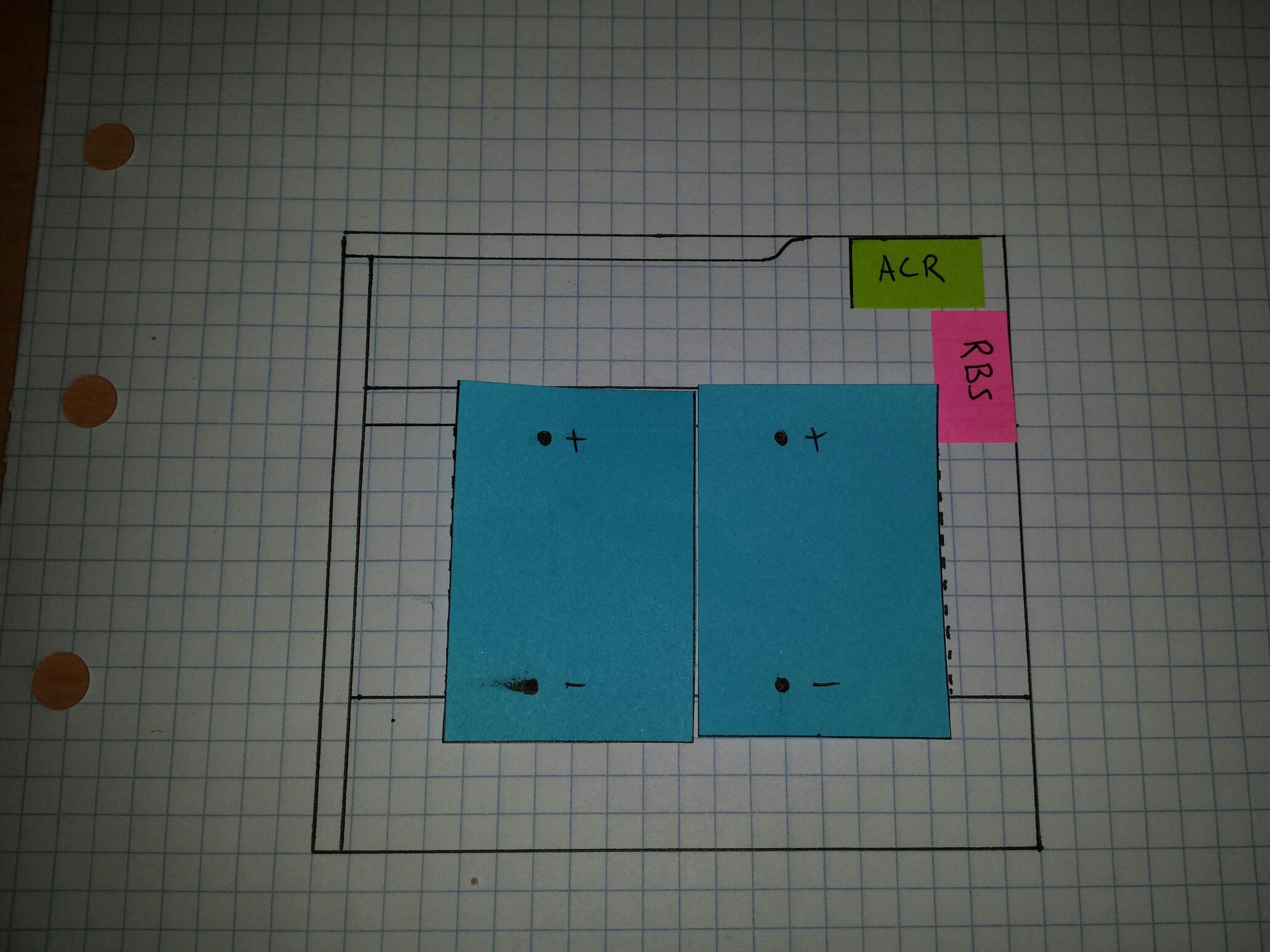
Option 1 for the ACR / RBS units is thus:
I'm hoping to get the RBS output closer to the fuse holder which will be mounted on the front wall of the box. I'm hoping to wing it a bit with this... not sure if I'll mount it horizontally as shown, or vertically.
With this arrangement, there should be enough room to slide the front-most battery towards the trans tunnel to get it out of the box without hitting anything, while still allowing grommets to be installed for cabling thru to the trans tunnel. Then the rear-most battery can be slid across should it need removal.
Finally,
I've come to the conclusion that the standard battery post clamps on the pumas are a load of crap, probably designed by the Earl of Nonsense at Solihull.
They use a nut which has an inverted cone to clamp down on a male cone which pinches on the terminal. Even swinging off it with a good size spanner, it's still loose. I think I'll have them changed before too long. Might also look at re-doing that factory mega fuse holder which will probably not work with the new batteries.
Well that's about all for now...
Until next time,
Cheerio.


 Reply With Quote


Bookmarks