Page 59 of 69 FirstFirst ... 9495758596061 ... LastLast
Results 581 to 590 of 690

Thread: Meet my 90, and share the adventure.

  1. #581
    Join Date
    May 2014
    Location
    Tamworth NSW
    Posts
    4,295
    Total Downloaded
    0

    The final connection

    This afternoon, I wired up the carling switches in the cab. I had it all labelled up and a wiring guide I'd done, so it was a simple matter of attaching a few wires for the switching side of the relays-
    1) 12V feed for switch- I picked this up off fuse 17 (High beam headlight) under the steering column.
    2) Illumination circuit- for the carling switches lighting when lights are on , and to indicate switch status. Picked 12V up off fuse 13- dash illumination under steering column
    3) Earth... plenty of those around. I was going to use the earth point on the firewall behind the dash, but may consider it when I'm there next. Mounted to the fuse board under steering column for now.

    I also used the add-a-fuse jumpers for the switches. I'll look at hard wiring it some time in the future. But for now it works and is operational. The installer of the radio just jammed a spade terminal in any old fuse alongside the blade fuse... D'oh. I'll get around to righting that wrong sooner or later, I'm sure.
    I had to run a few extra wires between the relays and dash (for the additional relay), as the extra relay output is not being used by the roof lights. I didn't exactly follow the traxide wiring for this part of the isntall, but it's just a duplication of what was already there.

    Pleased to say, that all the wiring over the past few posts all works as intended.

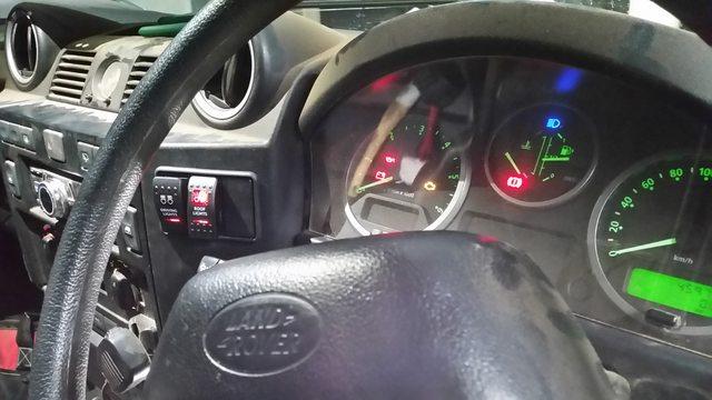
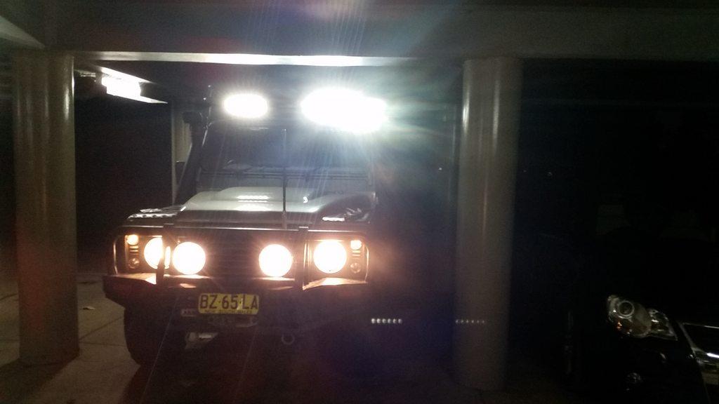
    New switch setup. Red matches the MUD led dome lights. You know, for teh night visions.
    -Mitch
    'El Burro' 2012 Defender 90.

  2. #582
    Join Date
    Jul 2009
    Location
    Melbourne, Victoria
    Posts
    193
    Total Downloaded
    0
    Quote Originally Posted by Toxic_Avenger View Post
    Yeah, I read it and thought it sounded a bit odd. Guilty of the old copypasta from the FM (as in RTFM).
    It's like the old story about how to disarm a bomb- 1) Cut the red and blue wires. 2) But first, cut the black wire.
    The devil is in the detail.
    Hi Mitch,
    The manual is not very clear in many places. The battery disconnect reads poorly in the manual.

    I had forgotten there was a sequence and your post reminded me about it. I have just been disconnecting battery leads and not even thinking about it. Luckily no ill effects so far. I will try to remember to follow what the manual says just in case.

    Excellent work on the wiring. I must admit you have encouraged me to look at tidying up some of the wiring on my Defender as some of it sadly looks like the photos of the wiring on your Defender before you sorted it. Live and learn.

    Keep up the good work.

  3. #583
    Join Date
    May 2014
    Location
    Tamworth NSW
    Posts
    4,295
    Total Downloaded
    0

    Modding the driving lights

    Just a little mod to the driving lights.
    The wiring from the headlight bodies in the IPF Xtreme units I have was a bit anaemic, and the connectors on the loom were not something that I could easily adapt to work with the 12 gauge (2.05mm2) wiring that was to feed them. The task was to put a new connector on the wiring leading to the driving lights, and re-wire the internals of the lights to take bigger wiring, and work with the 12 gauge wiring.

    The traxide kit has some spade terminals and white plug bodies to use, but I'm not a fan of them- how they look or how they are likely to collect mud, water and other things that hit the front of my car. As you've probably noticed, It's perpetually in a bit of a dirty state

    I've had a good run with Deutsch connectors in the past, and thought it was a good opportunity to 'step up' from the DTM series plugs to the DTP series for this little job. The DTM series is good for 16 gauge wire (ie your '10A and 15A' rated wires at your parts store, and can take about 10A per pin thru the plug. The DTP series takes 12 gauge wire (2.05mm2), and can take 25A. All deutsch DTM/DTP series are weatherproof, and skookum as frig. I like them. You mother likes them. What's not to love?

    Deutsch are probably the connector of choice for harsh conditions, factory fitted for harley davidson, CAT and lots of other gear. Deutsch also make some real cool panel mount connectors which might make an appearance in some future mods to the ex box. Still haven't decided if I'll go mild (ie getting accessory power into and out of ex box) or wild (ie full quick disconnect of OE wiring loom from ex box). I'll give it some thought in due course. Someone step up and be my guinea pig please?


    Anyway, TL;DR:

    Couldn't easily change this on the light:


    So soldered on some 12 gauge wire like so:

    This gave me thicker wire closer to the light globe, but also allowed me to use decent spec sealed connectors on wire of the same diameter on both sides of the join.

    Deutsch plug goodness, with none of the bad stuff

    Crimping the lugs down and assembling these connectors is strangely therapeutic.

    Works good:


    I also need to re-align the driving lights. Any tips here? I've got a pencil beam on the Driver's side, and a spread beam on the passenger side. Just eyeballing it, I've got the spread beam slightly to the LHS (maybe 1 or 2 degrees), and the pencil beam as dead on as I can manage by eye. Eyeballed the Y axis to parallell with road as best as I can manage.
    Ideally I'd be able to shine against a wall at distance or something, similar to how headlights are aligned. Thoughts / strategies on this appreciated.


    BONUS PIC!

    Some measurements for the relay mounting plate I made. Your milage may vary - not sure how precise LR manufacture/assembly is in this part of the vehicle, but this is what worked for me. Probably about the biggest plate you can squeeze thru the headlight hole.
    Material was 1.6mm gal sheet.


    2 holes should be drilled to M7, and are for the horn mounting bracket to bolt to. Fit the plate, then drill a few more holes along the RHS line to allow extra points of attachment if desired. I used riv nuts on the plate, however nuts welded on, or heaven forbid tek screws would work.

    Until next time,
    thank your mother for the rabbits.
    -Mitch
    'El Burro' 2012 Defender 90.

  4. #584
    Join Date
    Jan 2007
    Location
    Sydney
    Posts
    2,394
    Total Downloaded
    0
    Here are my thoughts on setting up driving lights. I'm really anal about this and I will usually spend ages getting it right. All just my opinion of course and others may disagree, but this is based on setting up many different sets of lights on various road and rally cars over the last 35 years of driving (and rallying). This is what I have found works for me for the type of driving I do.

    My first piece of advice is to ditch the spot. Having one spot and one spread gives you the worst of both worlds. Spots are really only any good for long straight roads such as out west. On any normal road (you know, one with bends and that) with one spot you end up with a bright circle of light that appears to head off in random directions relative to your direction of travel. I also think having one relatively bright area tends to make you stare at it whereas a broad even spread of light encourages you to look around. One spread doesn't really give you enough width to cover both sides of the road for a reasonable distance (ie from near the car to far away). Again, when going around corners the light is too narrow and heads off in a different direction to where you want to look. For the area you live in and the type of driving I suspect you would generally use these for, a pair of spreads would be a much better option. A small bright patch of light being thrown a few kilometres down the road may impress some people but they are ****house to drive behind unless you're crossing the Nullabor. A broad even spread of light is much easier to drive behind in most circumstances.

    As for the alignment, this really depends on the shape of the beam and what sort of driving you use them for. For example the way I like to set the lights up on the rally cars is to angle one driving beam slightly up and one slightly down because you spend a lot of time going over crests and through dips. Then we have a pair of very wide spread or cornering beams angled across the car, ie the left hand light shines to the right, so that you get some light in the direction you're travelling when you're going sideways. I avoid spots because I find them very distracting as they move all over the scenery. Besides there's really no point in seeing a long way as all you see is trees. This setup is no good for normal road driving though. With a pair of spreads I try to point them out to the sides just very slightly to get as wide a spread as possible but without getting any darker areas ahead. How much you can point them out will depend on the shape of the beam, in reality its generally not much if any at all as you still want the bulk of the light heading straight up the road.

    The trouble with a spot and spread combo is you are limited on what you can do (refer diatrabe above). Unless you live in an area where you only ever go around left hand bends and all the roos jump out from the left, all you can really do is point them straight up the road.

    A lot of this is stating the obvious but the only way to do it is to get out on a long, flat, straight bit of road. A paddock or carpark is no good as the lights need something to reflect off - you want to see the sides of the road. Set one lamp at a time, either disconnect one or stand in front of it while you're adjusting the other. Set them up so they look as far up the road as possible without pointing to the sky. Don't point them down too much so you have a bright spot on the road in front of the car as this will kill your distance vision.

    Then drive around with a spanner in the car for a few months so you can make adjustments. You'll never get it right the first time.

    Cheers,
    Jon

  5. #585
    Join Date
    May 2014
    Location
    Tamworth NSW
    Posts
    4,295
    Total Downloaded
    0
    Great info thanks Jon. Many things that I hadn't even thought of before you wrote them- the one light angled slightly up and one slightly down is a good idea.
    While I probably don't need as many lights as a rally car, I find what the previous owner fitted to the car works well enough for the times I need them.

    Took my first night drive last night to test the new light relay setup on road. Seems to be brighter. Can't really quantify it much more than than.
    -Mitch
    'El Burro' 2012 Defender 90.

  6. #586
    Join Date
    Jan 1970
    Location
    Free Again Thanks Dan
    Posts
    10,150
    Total Downloaded
    0
    We all have different ideas on what lights to run and each to their own
    For adjusting d/lights i get some cardboard folded to cover each head light and one for a d/light.
    I go find a isolated back road cover my head lights with the card board and one d/light and start the process of adjustment of either d/light.
    I like my 2 hid IPF spots it works for me as i find your headlights on H/beam light up the side of the road enough , When im doing 100 ks + I like to see a fare way in front as well as the side of the road .
    When i ordered my d/lights i had to make it specific i wanted 2 spots as you only got the combo in spread and spot.
    As i say what works for you or floats ya boat it is not gospel only personal preference in my opinion

  7. #587
    Join Date
    Jan 2007
    Location
    Sydney
    Posts
    2,394
    Total Downloaded
    0
    And I'm sure you won't be the last to disagree with me either.

    As I said it is what I have found to work for me for the driving I do, which is why I tried to put a big disclaimer at the top of the post - we all have different experience.

    I'm not trying to suggest there's anything wrong with using two spots if it suits the type of driving you do and of course there are situations where it will be better. I've just never found a single spot to be a good solution.

    Cheers,
    Jon

  8. #588
    Join Date
    Jan 2007
    Location
    Sydney
    Posts
    2,394
    Total Downloaded
    0
    Quote Originally Posted by Toxic_Avenger View Post
    I've had a good run with Deutsch connectors in the past, and thought it was a good opportunity to 'step up' from the DTM series plugs to the DTP series for this little job. The DTM series is good for 16 gauge wire (ie your '10A and 15A' rated wires at your parts store, and can take about 10A per pin thru the plug. The DTP series takes 12 gauge wire (2.05mm2), and can take 25A. All deutsch DTM/DTP series are weatherproof, and skookum as frig. I like them. You mother likes them. What's not to love?

    Deutsch are probably the connector of choice for harsh conditions, factory fitted for harley davidson, CAT and lots of other gear. Deutsch also make some real cool panel mount connectors which might make an appearance in some future mods to the ex box. Still haven't decided if I'll go mild (ie getting accessory power into and out of ex box) or wild (ie full quick disconnect of OE wiring loom from ex box). I'll give it some thought in due course. Someone step up and be my guinea pig please?
    I may put my hand up for that as I've been thinking along similar lines. I've got a few other wiring jobs that need some connectoring and the Deutsch stuff keeps appealing to me. However I keep getting put off by needing another several crimping tools whereas the AMP superseal stuff I usually reach for can be crimped with one of my existing collection. Have you spent a small fortune on crimping tools or have you found a way to adapt and overcome using a more conventional tool?


    Cheers,
    Jon

  9. #589
    Join Date
    May 2014
    Location
    Tamworth NSW
    Posts
    4,295
    Total Downloaded
    0
    Deutsch make a connector with the AMP style 'non insulated' crimp style terminals that you know and love.
    The crimp tools can be had online relatively cheaply (<$40), and TBH, you only really need a size 16 for the DTM terminals (which will be most of what you'd do on a car), and the size 12 crimp tool for the DTP series. 16 and 12 relate to the AWG size. Main issue is to match the wire gauge with the correct pin size and plug.
    -Mitch
    'El Burro' 2012 Defender 90.

  10. #590
    Join Date
    May 2014
    Location
    Tamworth NSW
    Posts
    4,295
    Total Downloaded
    0

    Pointless update. Is pointless.

    Pointless update.
    Not much has been happening. It has been a solid two weeks without tinkering. I'm getting itchy fingers.

    Headlight relays are working well. Had a birthday, had a flu, had no mods to install... so things have been quiet.
    Spent a whole day cleaning up the cluster**** of wiring, tools, and mess that I'd managed to create from the last project- so the other half is a bit more agreeable now that the house and man-cave (her home office / study / my makeshift shed) is in some degree of cleanliness. I need a rent-a-shed. Is there even such a thing?! Heck, I'd even time-share! FirstWorldProblems

    Not sure on next mods. Either a bombed-out Transfer-case with some goodies inside, or a BAS tune kit with the intercooler. Decisions...
    -Mitch
    'El Burro' 2012 Defender 90.

Page 59 of 69 FirstFirst ... 9495758596061 ... LastLast

Bookmarks

Bookmarks

Posting Permissions

  • You may not post new threads
  • You may not post replies
  • You may not post attachments
  • You may not edit your posts
  •  
Search AULRO.com ONLY!
Search All the Web!