

 Reply With Quote
Yes and Yes
Cost $12 plus Postage $12 a couple of months ago.

 OldBushie
Forgot to ask two other things...
1. Where did you fit the Traxide relay(s)?
2. Did the headlight bulbs end up being H4's?
MY15 Discovery 4 SE SDV6
Past: 97 D1 Tdi, 03 D2a Td5, 08 Kimberley Kamper, 08 Defender 110 TDCi, 99 Defender 110 300Tdi[/SIZE]
Moderator
Yes and Yes
Cost $12 plus Postage $12 a couple of months ago.
Mahn England
DEFENDER 110 D300 SE '23 (the S M E G)
Ex DEFENDER 110 wagon '08 (the Kelvinator)
http://www.aulro.com/afvb/members-rides/105691-one_iotas-110-inch-kelvinator.html
Ex 300Tdi Disco:
Moderator
I'll take some photos tomorrow but in the mean time:Originally Posted by dm_td5

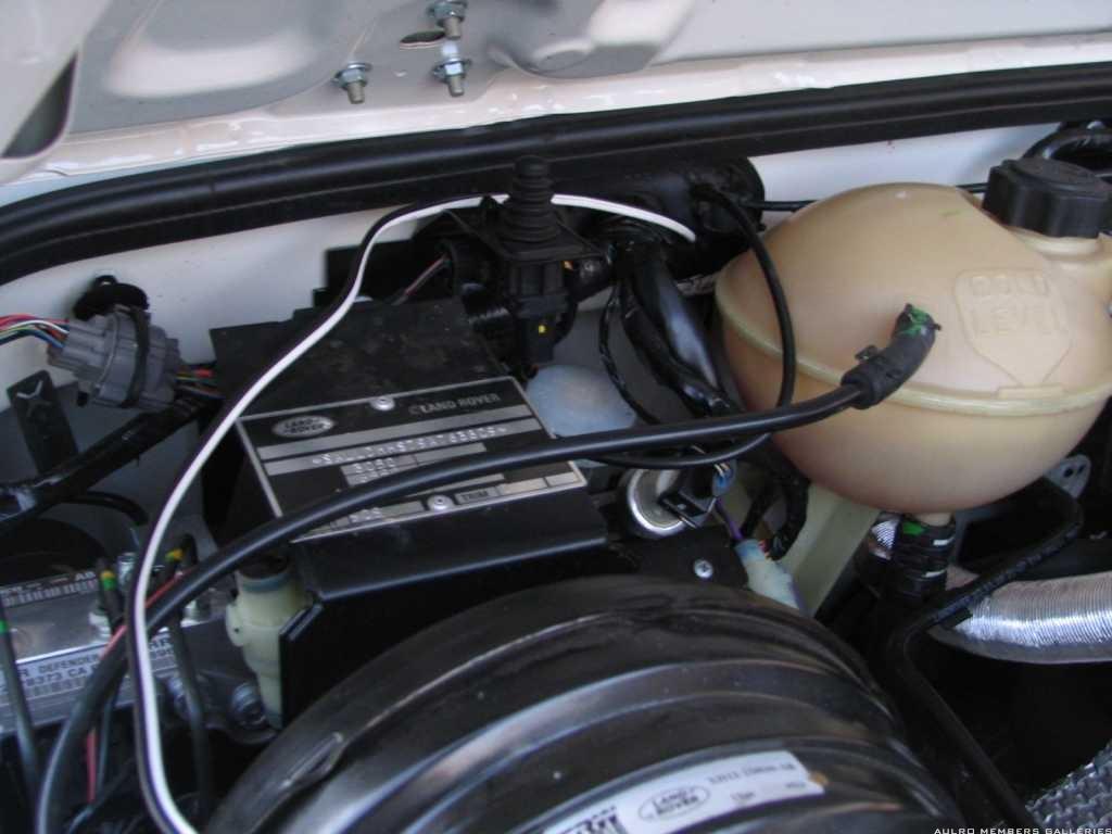
Front driver's side guard is easy to get to with the false intake removed. Plenty of room to work with drill access to the guard liner from the underside of the wheel arch
The sound deadening insulation was sacrificed to reveal the plastic guard liner. I mounted the 2 relays with 3 x 25mm M10 bolts (the middle one shared between the two relays) and mudguard washers and spaced them off the guard with large rubber gromits.
I took a thick earth from the AC compressor to one of the relay mounting bolts and fixed the other earths to this.
Getting the switch wiring through the fire wall was an interesting
exercise involving poking a straightened coat hanger through the large grommit pointing to the center of the vehicle. and then feeling for it as it hit the console (much luck involved there and a two person job). Taped the figure 8 wire to the coat hanger and pulled it through the firewall.
The lamps are H4.
Mahn England
DEFENDER 110 D300 SE '23 (the S M E G)
Ex DEFENDER 110 wagon '08 (the Kelvinator)
http://www.aulro.com/afvb/members-rides/105691-one_iotas-110-inch-kelvinator.html
Ex 300Tdi Disco:
OldBushie
Awww now you've gone and spoiled the surprise
Didn't expect it to be easy
Pic's would be good, I suspected you would have fitted it under the blank, there's not many other spots.
MY15 Discovery 4 SE SDV6
Past: 97 D1 Tdi, 03 D2a Td5, 08 Kimberley Kamper, 08 Defender 110 TDCi, 99 Defender 110 300Tdi[/SIZE]
Hmmm, bad news about alternator accessibility. Why is it that every time they upgrade a vehicle, it becomes harder to work on? Anyway, with 3 BS cable you should be right as rain.
Cheers,
Paul
YarnMaster
SubscriberPaul ; i s'pose in that situation there has to be a way to switch between output of the alternator and batteries because if you're alternator dies whilst you're driving at nightbut there will be times where you would want to run your lights whilst engine is shut off.
No, it is all automatic. If the engine is not running (or the alternator fails), the lights draw power from the battery.
When the alternator starts up, it first powers all the electrics of the vehicle, and then whatever is left of the alternator output is used to charge the battery.
Moderator
So some photos:
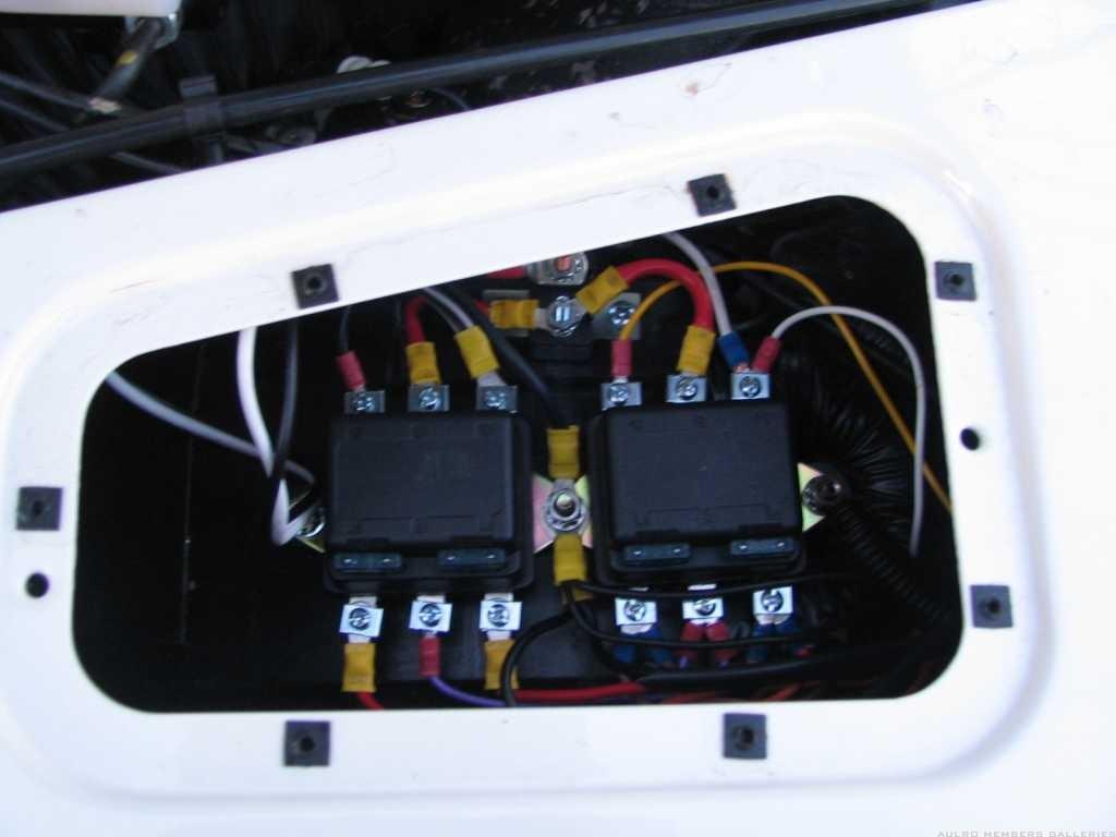
The relays in situ:
Note three bolts for the two relays with the earth connections on the centre bolt.
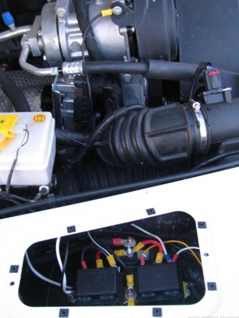
The relays and the earth connection to the AC Compressor shroud bolt. The 3 B&S cable is just above the relays connected via an additional circuit breaker to the short 8 B&S cable to the relays
The figure 8 switch wire (the black and white wire) going through the fire wall:
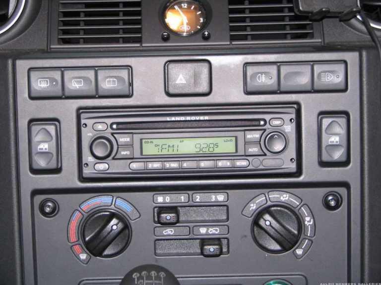
The reconfigured console switch arrangement:
All the rear window controls are now on the left and on the rhs the rear fog left and new driving light switch to the right closest to the steering wheel.
I still have some cable management to do.
Mahn England
DEFENDER 110 D300 SE '23 (the S M E G)
Ex DEFENDER 110 wagon '08 (the Kelvinator)
http://www.aulro.com/afvb/members-rides/105691-one_iotas-110-inch-kelvinator.html
Ex 300Tdi Disco:
Fossicker
Subscribera thread revival!
I'm planning on putting a Traxide Lighting Upgrade and Driving Light Kit into a TD5 Defender, and using the same switch above.
The YUG000540LNF switch has five pins; my friend google has identified them as being:
1 = earth switched
2 = +ve illumination (on with sidelights)
3 = earth
4 = redundant earth (matches pin 3)
5 = +ve control light (small orange led, feed from powered device)
Equally helpful on that site is a wiring diagram that shows the switch operation ...
http://www.landroveraddict.com/smf/i...opic=374616.20
Has anyone reconciled the traxide driving light wiring with this switch, so that you get a green LED for dash illumination and an orange LED when the DL are on?
Cheers
OldBushie
Hi willie and you will need to experiment with this but here goes
The short purple wire that runs from the driving light relay to the headlight relay, the end of it at the headlight relay needs to be disconnected and then that end needs to be connected to the B terminal on the driving light relay.
Next, the Black wire running from the driving light relay to the switch now needs to be connected to the ( 1 ) terminal of your Land Rover Fog Light Switch.
The White wire can now be used to turn on the Land Rover Fog Light Switch’s Orange LED by connecting it to ( 5 ) Land Rover Fog Light Switch and running it to L1 or L2 on the driving light relay.
The rest of the Land Rover Fog Light Switch wiring should be done as normal.
This should do what you are after.
PS willie, sorry I didn’t see your post earlier.
 Posting Permissions
| Search AULRO.com ONLY! |
Search All the Web! |
|---|
|
|
|


Bookmarks