Page 4 of 5 FirstFirst ... 2345 LastLast
Results 31 to 40 of 45

Thread: Fitting the Traxide Lighting Upgrade and Driving Light Kit to a 2007+

  1. #31
    Join Date
    Jan 2010
    Location
    Redlands, near Brisbane, QLD
    Posts
    67
    Total Downloaded
    0
    Hi all!

    I have a new Puma Defender, and am about to wire in some driving lights. I have got a Traxide kit, and the LR Front Fog Light switch.

    Going through the traxide wiring diagram and the suggestion from drivsafe, I can't help but think that if I move the short purple wire end at the headlight relay to the B terminal on the driving light relay, the driving lights will then not be activated only when High Beam is operating, but will in fact be able to operate all the time.

    Please bear with this lengthy description, but I am thinking:

    - Disconnect the short purple wire all together.
    - Terminate the white wire from the figure 8 cable to the Driving light Relay 'L1' or 'L2' terminal.
    - Extend a new cable from the 'S1' terminal on the Headlight Relay to the 'S' terminal on the Driving Light Relay.
    - Wire the switch in the dash with Earth on pin 3 and/or 4, Black wire (from figure 8 cable) on pin 1 and White wire (also from figure 8 cable) on pin 5

    This would provide power to activate the relay only when High beam is operating through 'S', the earth at the switch would provide the activation through 'S1' (and 'S2'), and the LED in the switch would be turned on with the driving lights.

    Is there anyone who has their setup working (and/or who can understand what I just explaned!) that can either confirm or shoot down my ideas?

    I intend to try the install this weekend (time permitting), so any advice would be appreciated. I do intend to take lots of photos during the install, and will try to post up a guide of what I did if it all pans out sucessfully.

    P.S. So far I can say the Traxide kit is a very well thought out kit, and I would reommend it to anyone.

  2. #32
    Join Date
    Jul 2003
    Location
    Sydney's gritty inner west (2204) and verdant Mount Wilson
    Posts
    7,445
    Total Downloaded
    0
    Forgive me if I misunderstand.

    I take it you want to be able to operate the driving lights independently of the high beam.

    A word of caution if this is the case:

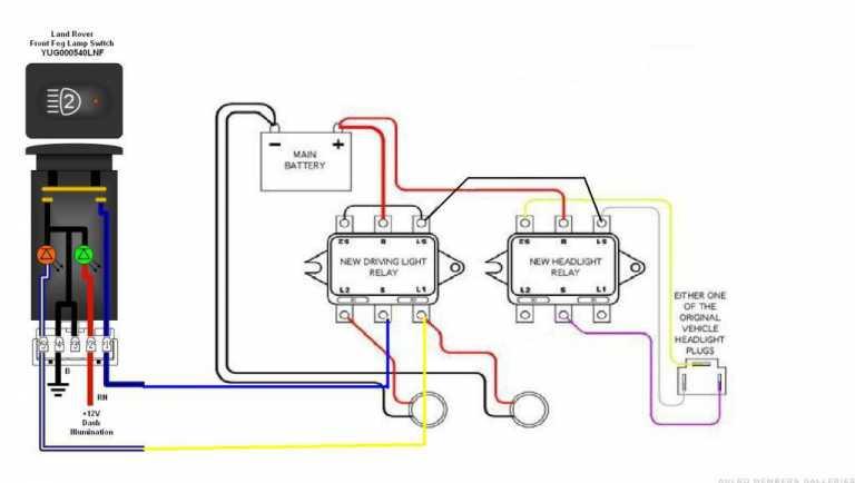
    Regulation requires that the driving lights must be dimmable with the high beam lights which is why the Traxide kit is configured this way.

    A dumb question:

    Why do you want to do this?
    Mahn England

    DEFENDER 110 D300 SE '23 (the S M E G)

    Ex DEFENDER 110 wagon '08 (the Kelvinator)
    http://www.aulro.com/afvb/members-rides/105691-one_iotas-110-inch-kelvinator.html

    Ex 300Tdi Disco:


  3. #33
    Join Date
    Jan 2010
    Location
    Redlands, near Brisbane, QLD
    Posts
    67
    Total Downloaded
    0
    You're forgiven . I specifically want to comply and have the Driving lights activate only when high beam is on.

    When looking at the wiring diagram and the suggestion from drivesafe (to modify his normal kit to work with the negatively switched LandRover switch), it appears to me that in that configuration the lights would indeed be able to operate without high beam being active.

    I may well be mistaken, which is why I am asking the question.
    There are no dumb questions!

    I hope this clarifies things?!

  4. #34
    Join Date
    Jul 2003
    Location
    Sydney's gritty inner west (2204) and verdant Mount Wilson
    Posts
    7,445
    Total Downloaded
    0
    Ah so...it's about getting the switch to light up:

    I've failed this test but haven't persevered.

    I can get the amber LED to illuminate when the driving lights are on but haven't pursuaded the green switch light to show up with the rest of the switches when they are illuminated.

    I did purchase a socket to fit the back of the switch to make life easier but the wiring puzzle eludes me.
    Mahn England

    DEFENDER 110 D300 SE '23 (the S M E G)

    Ex DEFENDER 110 wagon '08 (the Kelvinator)
    http://www.aulro.com/afvb/members-rides/105691-one_iotas-110-inch-kelvinator.html

    Ex 300Tdi Disco:


  5. #35
    Join Date
    May 2008
    Location
    Perth, WA
    Posts
    46
    Total Downloaded
    0
    The challenge is the switch itself - it is negative switching. The pins are below:

    1 = earth switched
    2 = +ve illumination (on with sidelights)
    3 = earth
    4 = earth (matches pin 3)
    5 = +ve control light (small orange led, feed from powered device)

    When the button is pressed, it joins (1) & (4) and closes a circuit with 5 (see pic below).

    With the dual headlight relay, S1 & S2 are the switches for L1/L2. The normal relay has these attached to the HB via a switch and a constant earth (S). You need to change this, making the earth the switch not S2/S2 (which are linked to the H.

    To make the switch work - you tap (4) into the dash earth header and use (1) as the relay's -ve and have the high beam from the headlight relay providing +ve to activate the driving light relay. Press the button, closes the earth switch, powering the relay.

    If you connect a wire from the DL (L1) to (5), the orange led will glow when the DL has power. If you connect (2) to the dash illumination, the switch will light up when the dash lights up.

    Lookie here for a butchered traxide diagram.


    Not my own work - I found a bunch of people who have struggled with this - most comprehensive post is here Defender2 - View topic - Switch fascia ... It did take me a handful of 10A fuses and an hour or so to put it all together for the Dual headlight relay

  6. #36
    Join Date
    Jan 2010
    Location
    Redlands, near Brisbane, QLD
    Posts
    67
    Total Downloaded
    0
    Thanks Willie. Your diagram corresponds pretty much with what I envisioned. That gives me great confidence!

    Unfortunately I didn't get the chance to get the driving lights in on the weekend. When crawling under the car to work out the best cable route from the battery, I noticed an oil leak between the gearbox and the transfer case. I didn't want to touch too much until I got it back to the dealer for repairs as I've only got about 1000k on the clock so far! (A lot further than some other people, but still.....).

  7. #37
    Trout is offline Master Silver Subscriber
    Join Date
    Dec 2006
    Location
    Boonah
    Posts
    232
    Total Downloaded
    0
    Quote Originally Posted by dmdigital View Post
    Interesting...I'm somewhat

    I thought this was YUG000540LNF


    Can I ask where you got it from?

    Can anyone suggest where in Aust.to get the female plugs that fit these switches. I have tried searching but I am having trouble working out exactly which plug it is and whether I also need to get special terminals to fit in the plastic holder (that then plugs into the switch). Also places I have found on-line only seem to sell these types of plugs in bulk packs.

    Thought about just soldering on wires direct to switch but there is not much room and I am worried about melting the plastic or ending up with a short circuit.

  8. #38
    Join Date
    Jan 2010
    Location
    Redlands, near Brisbane, QLD
    Posts
    67
    Total Downloaded
    0
    I don't know where in Australia, but I got mine from the UK:
    Dingocroft (Penn Rental Service Ltd t/a) Electrical Miscellany

    Part number: ZZplug01

    I bought two of them when I got mine, and I believe there would be no problems if you only want one.
    The part comes with the plastic insert to fit the back of the switch and also the lugs to terminate on the end of your wires to suit.

  9. #39
    Trout is offline Master Silver Subscriber
    Join Date
    Dec 2006
    Location
    Boonah
    Posts
    232
    Total Downloaded
    0

    Thumbs up

    Thanks. A sets of two is perfect....I got two switches just in case i needed more lights.

  10. #40
    Join Date
    Feb 2013
    Location
    sydney
    Posts
    102
    Total Downloaded
    0
    Quote Originally Posted by one_iota View Post
    The owner's manual says H7 60/55 w but I thought that H7's were a single filament bulb (two connections) used on lights with seperate low and high beam lamps

    I had a look at the lamp yesterday and it is definitely a twin filament (3 connections) so by my reckoning they are H4's and the "H7" is a misprint .
    I think LR screw that up ......
    mine MY13 puma are H4 bulbs..too

Page 4 of 5 FirstFirst ... 2345 LastLast

Bookmarks

Bookmarks

Posting Permissions

  • You may not post new threads
  • You may not post replies
  • You may not post attachments
  • You may not edit your posts
  •  
Search AULRO.com ONLY!
Search All the Web!