Hi Damo ... weighs a ton & a half!  ... and the bigger D31A I replaced the starting battery is double that!
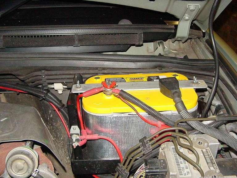
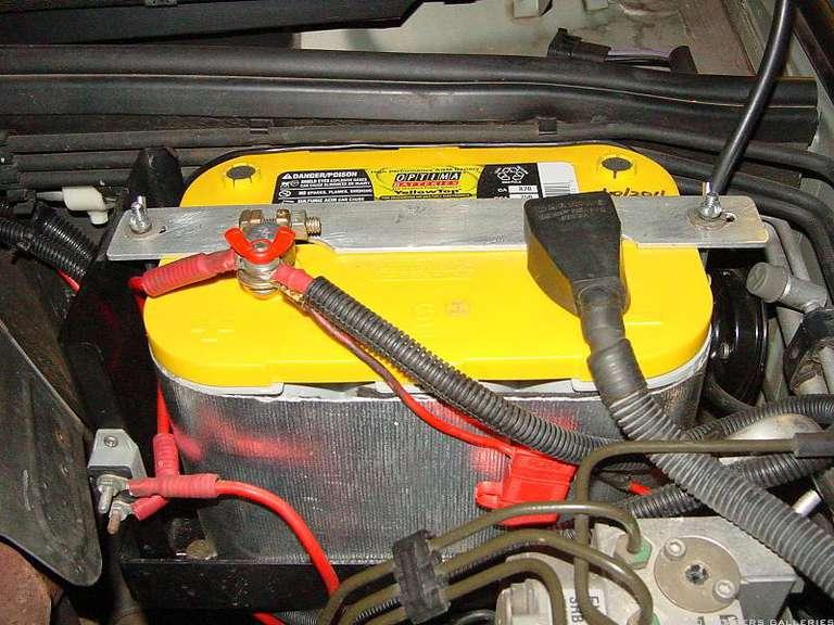
I'll try & take a few picks of my setup for you. It got it's first run over the 10th Anniversary gathering last weekend. Worked a treat.
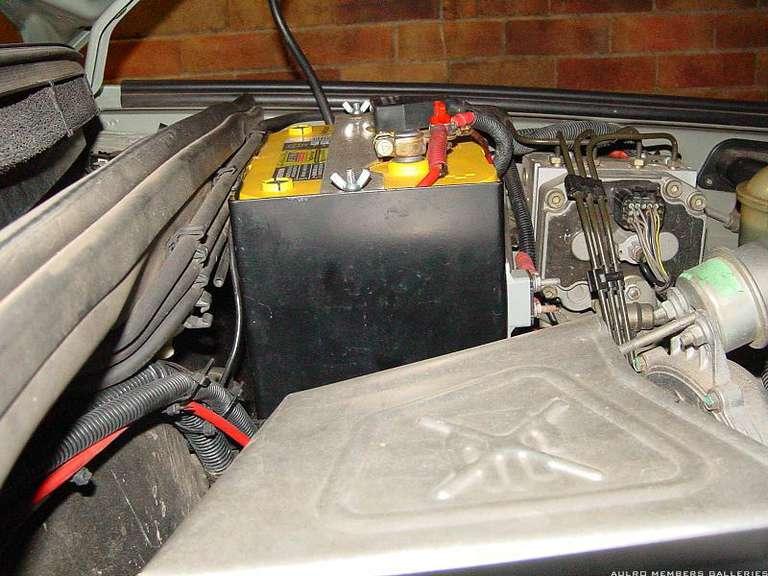
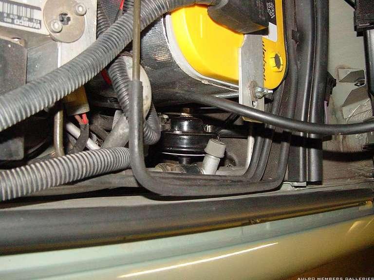
I just modified the ARB heatsheild (flipped it around 180deg), slotted the holes so it could move closer to the turbo, cut out the other side to allow the battery to move closer to the guard, and wrapped the battery in a Thermo-Tec battery heat sheild.
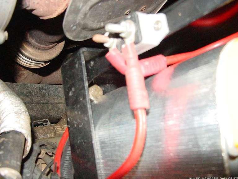
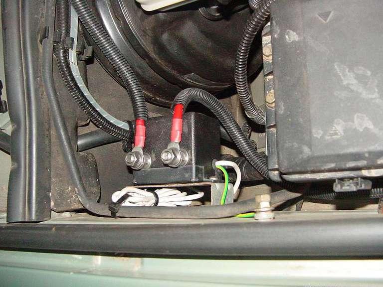
I put up a post (in tutorials I think) on where I mounted the USI-160 controller.
One thing I have immediatley noticed, is that with my old calcium starting battery & wet lead acid aux' battery, the voltmeter on the nanocom always ran at around 14.2-14.7v .... does the same with the Optima's installed for a short time, then the voltage falls all the way down to 13.5-13.8v .... meaning the battery's are fully charged. Over the weekend I noted that 24hrs use seemed to get put back into the batteries in about 15-20min's worth of driving.
I'll see if I can get some pic's to-night.
Kev..
2014 Isuzu MUX LST with fruit
2008 Isuzu D-Max
2015 Kimberley Kamper "Classic"
Gone ... 2004 D2a Td5 Auto "Classic Country" Vienna Green


 Reply With Quote

 .
.

") (less chance of buggering something up!)
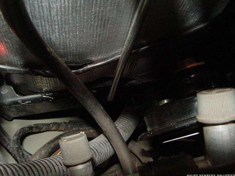
(less chance of buggering something up!) .... then went out the next moring and bought a burr ... too bloody hard the way I started. It's a slow job, and you don't want to slip and take out the a/c lines in that area !

Bookmarks