Page 2 of 2 FirstFirst 12
Results 11 to 16 of 16

Thread: Electric Wing Mirror Repairs.

  1. #11
    Join Date
    Aug 2010
    Location
    Bermagui
    Posts
    477
    Total Downloaded
    0
    I also have the exact same problem but i gave up / found something more important to fix.

    I did find a few very flat wires pinched between the two outer casings where the wires run from inside to outside. I also found that i was not getting power to one of the motors. I repaired one badly squashed wire but to no avail.

    Ill be watching this thread with interest.

    Sent from my GT-I9100T using Tapatalk 2

  2. #12
    Join Date
    Feb 2011
    Location
    Brunswick, Victoria
    Posts
    3,778
    Total Downloaded
    0
    Quote Originally Posted by accident94 View Post
    I must get myself one of theese RAVE cd's....

    The poke and pray does not bode well for my disco's internals methinks.

    also, i am 'alledgedly' studying electrical engineering as part of my degree... and i can barely understand theese diagrams!
    still beats the scattergun approach
    Before I fitted the stereo remote controls I checked the steering column wiring loom to make sure the right wires were in place. It was obvious that a "pro" had done a variant of poke and pray - every wire in the loom had been probed with a insulation piercing probe. Looked a bit like a tear along the dotted line job.

    If you use the electrical library and wiring diagram together you'll be able to nut them out.

    The introduction in the electrical library is worth reading as this explains most of the information found in the rest of the electrical library and wiring diagram PDFs.

    The wiring diagram has a couple of charts showing which pins are connected when you move the switch in a particular direction. The chart is in the format of c0066-1 <-> c0066-2. There are two ways to use this. You can simply go off the wiring diagram and use the color codes to identify the correct wires, or you can look up connector 0066 in the connector views section of the electrical library, which shows the location of the connector and the pin numbering. The number is giving for looking at the face of the connector, rather than the wiring side.

    RAVE recommends that you back probe wires for testing. Back probes are similar to standard test probes but the point is much finer - less than 1mm diameter - and allows the probe to be inserted into the back of the plug while it's still connected. If you are careful you could probably get away with using pins or fine piano wire.

    By testing for continuity between the pins shown in the chart you can verify if the switch is the problem or not.

    If the switch passed this test you'd move on to checking wiring paths between switch and mirror using the wiring diagram and connector views to identify any intermediate connectors. Start off with end to end, then if there are continuity problems you can isolate which section the problem lies in by checking between the intermediate headers.

    Cheers
    Paul

  3. #13
    Join Date
    Aug 2012
    Location
    Perth
    Posts
    32
    Total Downloaded
    0
    ok, after doing some continuity testing on the wires, i've discovered that there is no connection between the two (joined) common ground wires on the passenger mirror, and the common ground on the multiplug. This indicates to me that the issue is in the part of the circuit hilighted below:


    So i'm going to need to figure out where that wiring loom runs, and where the 'HEADER 0285 (K109) is' (also circled in the above diagram).

    I also did continuity testing on the switches. (the pins on the switch are actually numbered - it's moulded onto the casing inside the plug on the switch) Curiously, when switched to 'left' my switch follows the table for the drivers side mirror and vice versa.... the wiring colour codes are also switched, and when the diagram says something leads to the drivers side, it always leads to the passenger side.
    This seems odd, and i'm not sure if it means my car is wired backwards or the schematics are innaccurate (or i'm doing something wrong :P ). It seems to work fine though.... Food for thought that.


    Anyway, for the benefit of those who might also have this issue, i'll try and summarise what i've done, and more importantly what's been succesful in a sort of troubleshooting guide and edit it into the original post.

    *edit*

    No i won't... turns out i can't edit the original post for some reason....

    *edit*

    i figured out why it's backwards... that schematic is for a LHD model... XD
    Awkward.

  4. #14
    Join Date
    Aug 2012
    Location
    Perth
    Posts
    32
    Total Downloaded
    0
    ok, so it is the ground wire.

    I'm not sure where in the wire the break is, but bypassing the wire altogether fixes the issue.

    so now i'm faced with the choice of replacing the wire or simply running a new one in a permanent bypass.

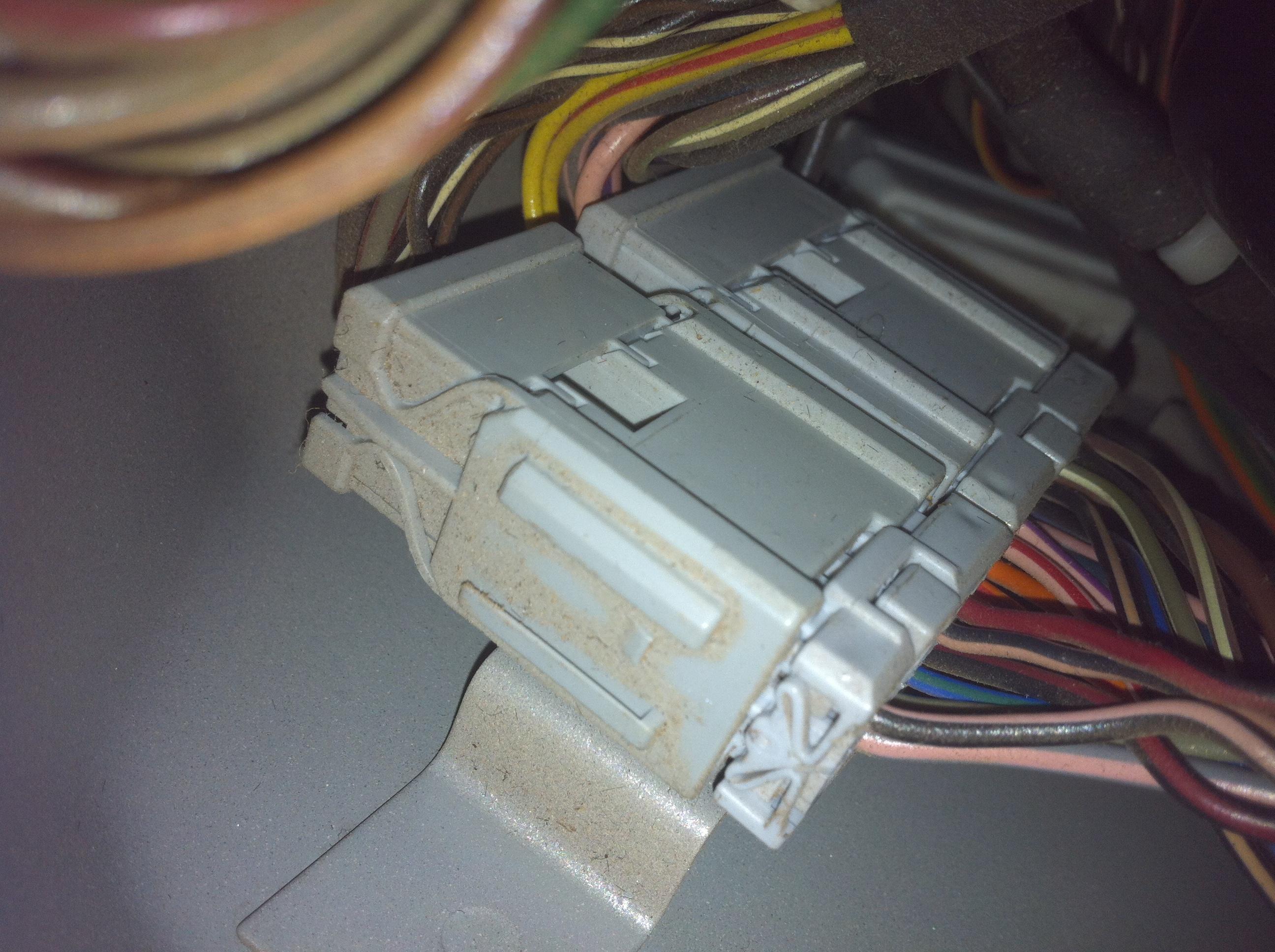
    this is where the door harness connects to what i assume is the main harness. (the top plug)
    where it goes from here i cannot tell.


  5. #15
    schuy1 Guest
    Have you bypassed the ground wire from mirror to the connecting plug? My thoughts are the wire may be damaged from the flexing of opening and closing door?

  6. #16
    Join Date
    Feb 2011
    Location
    Brunswick, Victoria
    Posts
    3,778
    Total Downloaded
    0
    Quote Originally Posted by accident94 View Post

    So i'm going to need to figure out where that wiring loom runs, and where the 'HEADER 0285 (K109) is' (also circled in the above diagram).
    Easiest way to find the header location is to look at the C number of the connected wires.

    It's going to be hard using the NAS diagrams as the numbering is different. On the RHD vehicles the header is number 0292. It is actually a join in the main loom, and is taped over. I'd put that last on the list of suspects. The connector pair C0464/C0733 which is in the passenger a-pillar sounds like the set you've identifed.

    I patched in power fold wiring to the existing loom a month or so back, and it isn't too bad pulling wires. I took off the door trim, and pulled the mirror connectors through in the hole in the door frame, which then allows you to work on the run up to the mirror without being a contortionist.

    If you are going to run new wiring I'd suggest soldering the new to the one end of the old and use the existing wire to pull the new run throught the loom. The individual terminals are retained by a small plastic tang. You can lift this by inserting a small jewelers screw driver above the terminal from the front of the connector. It's a bit hard to describe but there is an obvious space in the connector body, and you slide the screwdriver along the top of the terminal. If you have it right a gentle pull on the wire will release the terminal.

Page 2 of 2 FirstFirst 12

Tags for this Thread

Bookmarks

Bookmarks

Posting Permissions

  • You may not post new threads
  • You may not post replies
  • You may not post attachments
  • You may not edit your posts
  •  
Search AULRO.com ONLY!
Search All the Web!