


 Reply With Quote
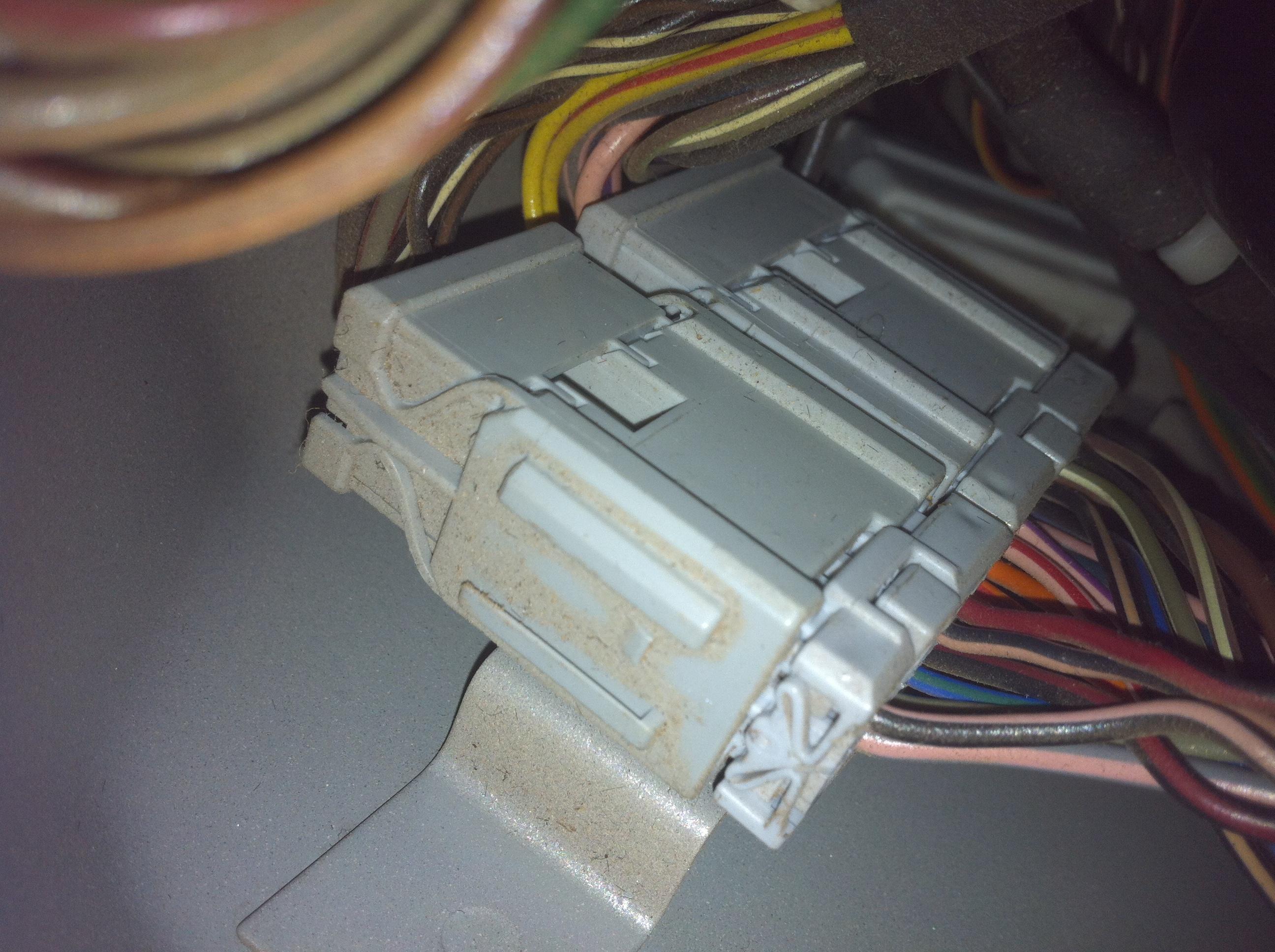
Before I fitted the stereo remote controls I checked the steering column wiring loom to make sure the right wires were in place. It was obvious that a "pro" had done a variant of poke and pray - every wire in the loom had been probed with a insulation piercing probe. Looked a bit like a tear along the dotted line job.Originally Posted by accident94

If you use the electrical library and wiring diagram together you'll be able to nut them out.
The introduction in the electrical library is worth reading as this explains most of the information found in the rest of the electrical library and wiring diagram PDFs.
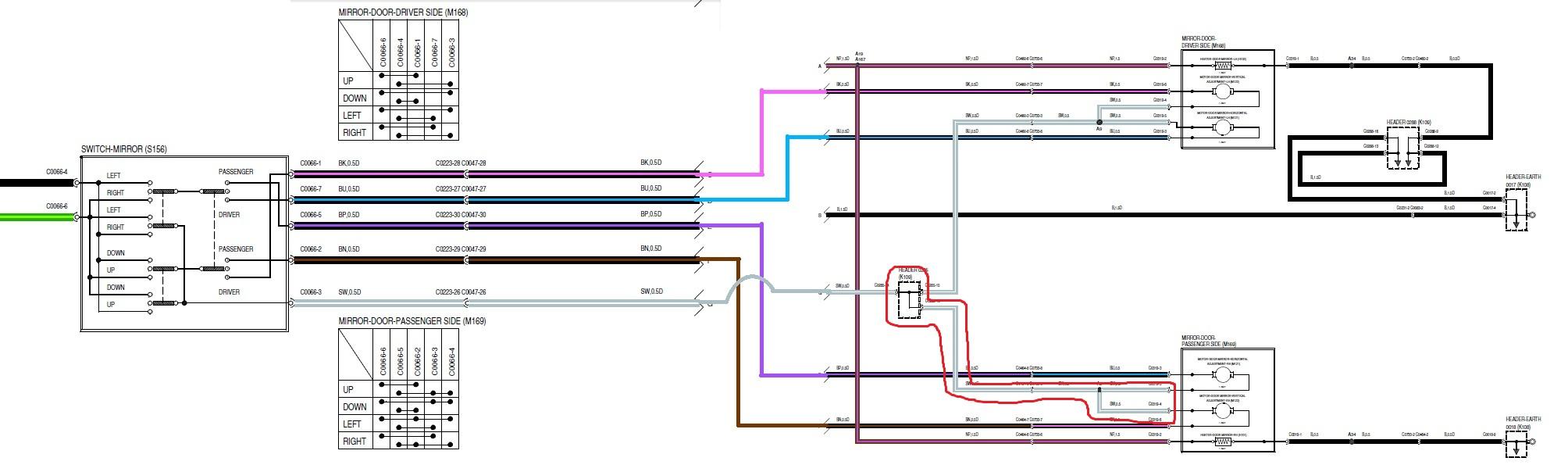
The wiring diagram has a couple of charts showing which pins are connected when you move the switch in a particular direction. The chart is in the format of c0066-1 <-> c0066-2. There are two ways to use this. You can simply go off the wiring diagram and use the color codes to identify the correct wires, or you can look up connector 0066 in the connector views section of the electrical library, which shows the location of the connector and the pin numbering. The number is giving for looking at the face of the connector, rather than the wiring side.
RAVE recommends that you back probe wires for testing. Back probes are similar to standard test probes but the point is much finer - less than 1mm diameter - and allows the probe to be inserted into the back of the plug while it's still connected. If you are careful you could probably get away with using pins or fine piano wire.
By testing for continuity between the pins shown in the chart you can verify if the switch is the problem or not.
If the switch passed this test you'd move on to checking wiring paths between switch and mirror using the wiring diagram and connector views to identify any intermediate connectors. Start off with end to end, then if there are continuity problems you can isolate which section the problem lies in by checking between the intermediate headers.
Cheers
Paul

Bookmarks