
Originally Posted by
steveG

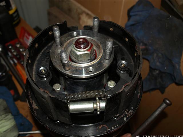
As a side note, the front output flanges are the same on all RRC and 110 LT95's. The only one that is different is the Stage1 box which has much larger flange since it had a double cardan joint in the front shaft.
In my case both of my boxes are from Stage 1's. Since its going into a 110, all I had to change was to remove the Stage1 flange and fit a flange from a 110/RRC LT95.
Steve
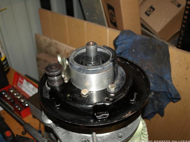
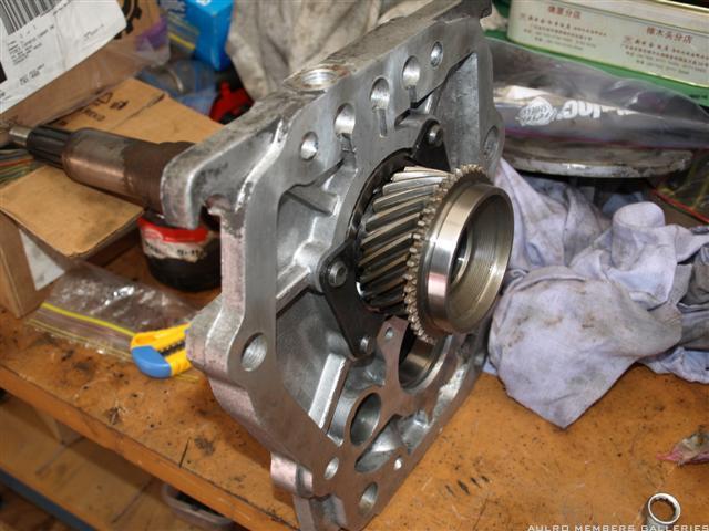
Steve, Something to look out for here is that the stage 1 box has a longer front output shaft and front output housing than the 110 and RR box. If you are going to use this box in a 110 you will probably have to use the stage 1 drive flange and front driveshaft or make up a shorter front shaft.
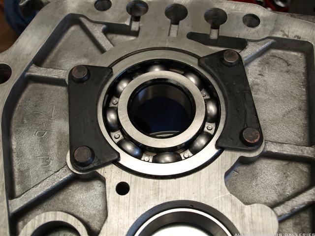
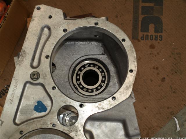
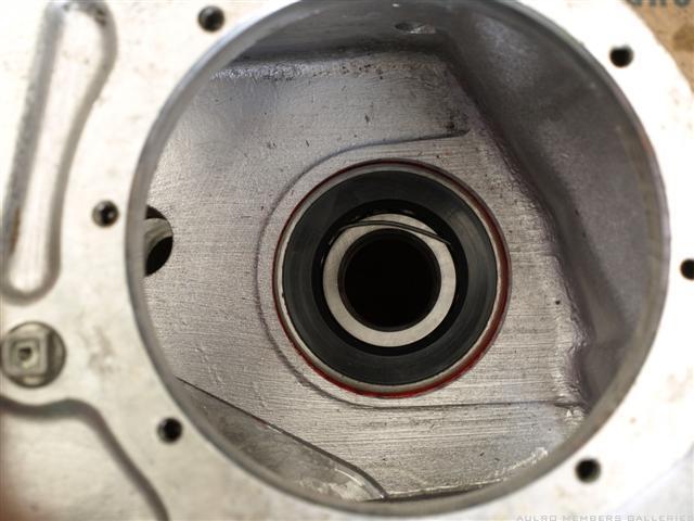
Another trick with the mainshaft seal is to tilt it slightly in at the top as you fit it and it will go in easier. As you have noticed the housing where it fits is tapered in thickness. Putting the rear main bearing in the freezer for a while before you fit it is usually sufficient to get it in the housing without needing the housing heated up.
Cheers......Brian
1985 110 V8 County
1998 110 Perentie GS Cargo 6X6 ARN 202516 (Brutus)


 Reply With Quote
 )
)


")


Bookmarks