Page 8 of 14 FirstFirst ... 678910 ... LastLast
Results 71 to 80 of 134

Thread: LT95 rebuild for beginners

  1. #71
    Join Date
    Sep 2008
    Location
    Geelong, VIC
    Posts
    4,442
    Total Downloaded
    0

    Mainshaft

    Assuming you've already stripped the mainshaft, inspected and sourced any parts as required.
    Now its time to put it back together.

    The synchros can be a bit tricky to assemble, but I found the easiest way for me was to set them up so there was a slight side load on the spring, hold the inner and outer parts, then at the same time push the ball on and push the sliding blocks under the outer ring.
    They seemed to stay in this position reasonably well while you worked on getting the next one in, and once all 3 were done you can centralise the whole lot and it becomes stable.

    If you don't lose any of the balls, then you're doing better than I did - I lost 2.
    Do yourself a favour and accept that you will lose some, so buy a few spares when you're at the bearing shop. They are only a few cents each.

    Here's a photo of my starting position before pushing the ball in. You can see the spring bent over slightly - it really wants to sit under the outer ring - which it will do once you push the ball in:


    There is a small cup seal in the front end of the mainshaft - make sure you replace it (you can also see how the assembled synchro should look):


    Assemble all the other parts onto the mainshaft (except the rear spacer, output gear, shim and circlip - as these go into the transfer case).

    It should now look like this:


    At this stage, I put the gearbox case up on the bench and stood it up vertically, front of the box at the top.
    Its now just a simple matter 
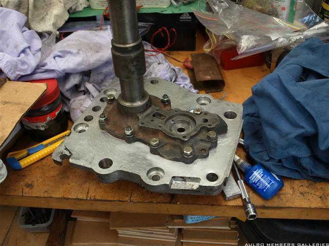
of lowering the shaft and gears into the case and through the rear main bearing. The problem is that there is a web/bridge in the case that prevents you lowering it straight in, so you have to drop first gear and its bearings in first, then assemble them back onto the shaft inside the box.
    Don't use the outer synchro rings as handholds or you risk them coming apart and disappearing into the shed somewhere (at which point you start again).
    Its just a fiddly job and you have to persevere until it all drops into place. You'll know when it does as the front end of the shaft will be below the face of the case, and you wont be able to slide first gear up the shaft any more.

    At this stage you'll be quite glad it looks like this:


    Now, from the transfer case side, slide on the spacer (with some loctite to seal it), the output gear, appropriate size shim, and fit the circlip.

    I modded my spacer with a small dab of weld to prevent it turning on the shaft. The weld sits into the shaft spline. Apparently this is one of the causes of oil migration from the transfer to the main box as the rotation pumps oil down the shaft. Another way of achieving the same thing is to make a pin that fits in one of the holes in the side of the spacer - and locates in the spline.
    To me the dab of weld was much simpler, and will achieve the desired result.


    And all assembled (actually still need to fit the circlip):


    Steve

  2. #72
    Join Date
    Oct 2010
    Location
    Dixons Creek Victoria
    Posts
    1,533
    Total Downloaded
    0

    Lightbulb

    Just a couple of points at this stage Steve.
    If the synchro hubs have been dimantled, in many instances they won't reassemble just on any splines.Either mark the hub and collar before dismantling,as shown on your front view photo of 3rd/4th synchro or try assembling one spline at a time to find a match that slides together smoothly before fitting springs and balls.
    Question. are you going to have section on how to identify components that may need replacing?

    Anyone following this rebuild guide would realize by now that aside from the transfercase internals, these are not the type of transmission that lends it self to being fixed up at the bottom of some remote sand dune or similar, so in the interest of vehicle and occupant survivability I offer an untried and tested modification suggestion.
    I have never owned a vehicle with an Lt95, but thought if I ever did that I would look at modifying the front of the mainshaft and the input shaft to accept either a taper roller bearing to replace the parrallel roller pilot bearing, or fit a torrington needle thrust bearing behind the parrallel roller bearing.
    I've seen quite a few mainshafts where the spline segments have broken off behind the circlip groove that retains the t/case mainshaft gear in place,allowing the mainshaft to float forward with disastrous results.I feel the afore mentioned modification would relieve the circlip of some of the hammering it cops from the main gearbox gears from drive to coast.In the event of a circlip or groove failure only the mainshaft gear could float(this could be addressed too)rearwards in reverse gear,but the main gearbox shouldn't suffer any damage.
    Wagoo.

  3. #73
    Join Date
    Aug 2006
    Location
    Melbourn(ish)
    Posts
    26,497
    Total Downloaded
    0
    Do not accept that you will loose some of the balls during assembly. They will turn up in the most inconvenient of places like in the race of the bearing you have installed or down under the cup of a seal that doesn't have a shaft in it or in the intake port to the oil pump or.........

    most of these have very very entertaining results, providing you dont own the vehicle it happens to.

    if you cant assemble them without loosing the balls go and purchase some of the very large ziploc bags or a matress bag or something large plastic and clear, insert all the parts into that and then assemble it inside the bag.

    on doing the weld thing on the spacer while it works is not a good idea.. welding hot enough to get a good penetration may distort the spacer and welding cold enough leaves the chance of the weld popping off. A roll pin and the use of a medium bearing mount (603) to secure both the pin and the spacer during final assembly is a safer bet.


    to aid lowering the shafts in I use hootchi cord wrapped around the bottom of the shaft and wrap the cord round my wrist so that the weight of the shaft is on the cord and my hand controls the movement of the shaft once its in just unwind the cord and then it will sit down neatly.
    Dave

    "In a Landrover the other vehicle is your crumple zone."

    For spelling call Rogets, for mechanicing call me.

    Fozzy, 2.25D SIII Ex DCA Ute
    Tdi autoManual d1 (gave it to the Mupion)
    Archaeoptersix 1990 6x6 dual cab(This things staying)


    If you've benefited from one or more of my posts please remember, your taxes paid for my skill sets, I'm just trying to make sure you get your monies worth.
    If you think you're in front on the deal, pay it forwards.

  4. #74
    Join Date
    Sep 2008
    Location
    Geelong, VIC
    Posts
    4,442
    Total Downloaded
    0
    Wagoo:

    Yes, I should have documented the inspection stage straight after the teardown. Probably best to leave it now and cover it at the end as a separate section after the reassembly. Not ideal but better than mixing it with the remainder of the reassembly.
    I've actually completely assembled this box now (just catching up on the documenting), but have another, somewhat tired, ex Stage1 Isuzu box stripped on the bench that will go back together as a spare so I should be able to supply pictures of both good condition, and well used parts..

    I'm very interested in the mainshaft failures you've seen, as I haven't come across any info on it being an issue.
    Was there any particular pattern to the failures - eg high HP engines, competition work, aggressive driving style, large tyres, lots of towing, high mileage vehicles etc, or were they just random failures.
    I could see that in worn boxes where the clearance on the mainshaft had increased that there could be resulting impact loads on the circlip, but wouldn't have thought it would occur on a box in reasonable condition.

    Steve

  5. #75
    Join Date
    Sep 2008
    Location
    Geelong, VIC
    Posts
    4,442
    Total Downloaded
    0
    Quote Originally Posted by Blknight.aus View Post
    Do not accept that you will loose some of the balls during assembly. They will turn up in the most inconvenient of places like in the race of the bearing you have installed or down under the cup of a seal that doesn't have a shaft in it or in the intake port to the oil pump or.........

    most of these have very very entertaining results, providing you dont own the vehicle it happens to.

    if you cant assemble them without loosing the balls go and purchase some of the very large ziploc bags or a matress bag or something large plastic and clear, insert all the parts into that and then assemble it inside the bag.

    on doing the weld thing on the spacer while it works is not a good idea.. welding hot enough to get a good penetration may distort the spacer and welding cold enough leaves the chance of the weld popping off. A roll pin and the use of a medium bearing mount (603) to secure both the pin and the spacer during final assembly is a safer bet.


    to aid lowering the shafts in I use hootchi cord wrapped around the bottom of the shaft and wrap the cord round my wrist so that the weight of the shaft is on the cord and my hand controls the movement of the shaft once its in just unwind the cord and then it will sit down neatly.
    Good point about the final location of the missing balls. I'll 'fess up to being a bit cavalier about losing them and also to having mentally rewound the entire reassembly to convince myself that the little suckers weren't inside the box somewhere. I'm happy that I know where each one went - just they aren't retrievable without a lot of effort (and they aren't in the g'box).
    The zip-lock bag idea is a great one.

    With pinning the spacer - would you put the roll pin in one of the extractor holes, or drill a separate hole?
    Reason I ask is that the extractor holes are slightly larger than the spline grooves, so a roll pin isn't going to go fully into the groove unless you taper it slightly on the end. Maybe the chamfer on the end of the roll pin is enough - but just didn't seem quite right when I looked at it.

    I accept the theory, but reckon you'd have to go pretty hard to distort the spacer with a small bit of weld. Its a pretty solid item and I've seen them with fully welded pins in an extractor hole with no dramas.

    With the hootchie cord (admit I had to Google it to confirm what it was), can you actually get the shaft in with the 1st gear fully up the shaft?
    Seemed to me that the gear would still be too high up and hit on the case bridge when you tried to get the shaft through the rear bearing.

    Steve

  6. #76
    Join Date
    Aug 2006
    Location
    Melbourn(ish)
    Posts
    26,497
    Total Downloaded
    0
    In the past I've drilled a seperate hole and pinned through that, this leaves the extractor hole good to use later if you need to.

    you can drop the shaft in with the gear in place past the web but trust me its a tetris slidey game you dont want to play with. its easier to insert the firstgearset then slide the rest into place. ( you have to have the gear assembly down on the splines of the shaft one hand in the gap where the layshaft goes and the other coming in through the top cover to support the shaft assembly by the gears and not the 4th syncro.) its easier to drop it in in sections using some improvised tooling.

    theres a couple of ways of inserting the first gear set, usually I hang them all on a figure 8 of wire thats had the bottom cut and turned outwards slide them down squeeze the wire and they all sit in place, a bit of fiddling with a scribe will get a nice eyeball line then drop the rest in place.

    you can also slide them up a wooden dowel poke the down in place through the back bearing then slide the gearset down and use the dowel to center everything up before sliding the rest into place.

    when it comes to sliding the mainshaft assembly into the first gearset you can also use dental floss, 5-10 turns around the whole assembly (go around the bottom and as you pass up past the gears lay the floss in the vallies between teeth then over the top and down through the teeth around the bottom again. keep all the turns on one side of the shaft so that you can unwrap it in one piece I find it easier to drop it down into the layshaft area.

    on the welding front... that comments aimed mainly at beginners who may not have a mig and might be tempted to try it with a stick welder. A competent welder should be able to spot in a plug weld and not fill the hole up to the point where the extractor wont grab the sleeve.
    Dave

    "In a Landrover the other vehicle is your crumple zone."

    For spelling call Rogets, for mechanicing call me.

    Fozzy, 2.25D SIII Ex DCA Ute
    Tdi autoManual d1 (gave it to the Mupion)
    Archaeoptersix 1990 6x6 dual cab(This things staying)


    If you've benefited from one or more of my posts please remember, your taxes paid for my skill sets, I'm just trying to make sure you get your monies worth.
    If you think you're in front on the deal, pay it forwards.

  7. #77
    Join Date
    Oct 2010
    Location
    Dixons Creek Victoria
    Posts
    1,533
    Total Downloaded
    0
    Quote Originally Posted by steveG View Post
    Wagoo:

    I'm very interested in the mainshaft failures you've seen, as I haven't come across any info on it being an issue.
    Was there any particular pattern to the failures - eg high HP engines, competition work, aggressive driving style, large tyres, lots of towing, high mileage vehicles etc, or were they just random failures.
    I could see that in worn boxes where the clearance on the mainshaft had increased that there could be resulting impact loads on the circlip, but wouldn't have thought it would occur on a box in reasonable condition.

    Steve
    Thinking back,for every vehicle I had to rebuild the transmission on, there would have been 6 trans that came in for overhaul as exchange units, so it was difficult to ascertain individual working conditions on each I box saw.
    For every vehicle that suffered a mainshaft failure of this type there were probably hundreds, maybe thousands that didn't.But having seen quite a few failures, and noting the consequences, bearing in mind that these are big heavy one piece transmissions that are extremely difficult to remove from the vehicle to affect bodge repairs in a remote location,I would personally attempt the suggested modification at the overhaul stage if I planned on doing a lap of OZ or crossing the Simpson etc.
    I simply couldn't afford the towing bill or to pay another mechanic to fix up the truck in some place like Birdsville.
    The modification if feasible would increase my peace of mind level by a couple of hundred percent.
    I've got some bits in the shed. I'll measure them up when I get home, and see whatsuitable size bearings are available.
    Wagoo.

  8. #78
    Join Date
    Sep 2008
    Location
    Geelong, VIC
    Posts
    4,442
    Total Downloaded
    0
    Quote Originally Posted by wagoo View Post
    Thinking back,for every vehicle I had to rebuild the transmission on, there would have been 6 trans that came in for overhaul as exchange units, so it was difficult to ascertain individual working conditions on each I box saw.
    For every vehicle that suffered a mainshaft failure of this type there were probably hundreds, maybe thousands that didn't.But having seen quite a few failures, and noting the consequences, bearing in mind that these are big heavy one piece transmissions that are extremely difficult to remove from the vehicle to affect bodge repairs in a remote location,I would personally attempt the suggested modification at the overhaul stage if I planned on doing a lap of OZ or crossing the Simpson etc.
    I simply couldn't afford the towing bill or to pay another mechanic to fix up the truck in some place like Birdsville.
    The modification if feasible would increase my peace of mind level by a couple of hundred percent.
    I've got some bits in the shed. I'll measure them up when I get home, and see whatsuitable size bearings are available.
    Wagoo.
    What about just modifying the rear circlip groove so that its deeper and therefore less likely to shear off. Maybe deep enough so that it actually goes into the solid part of the shaft (ie deeper than the splines).
    That part is a larger diameter than the roller bearing in the rear cover, so probably wouldn't decrease the strength of the shaft itself.

    My thought on modifying the front end of the mainshaft is that if the mod fails you're probably just as screwed as if the back end failed.
    Given the relatively low failure rate you've indicated above it might actually decrease the box reliability.

    On the boxes that you worked on, were there cases of partially failed/cracked splines in that circlip area, but that hadn't resulted in a full failure? If so, then a regular inspection of that area (easy to do) would likely detect an impending failure.

    Steve.

  9. #79
    Join Date
    Oct 2010
    Location
    Dixons Creek Victoria
    Posts
    1,533
    Total Downloaded
    0
    Generally, any transmission shaft that is subject to bending loads will concentrate stress at sharp corners or the transition points of changes in diameter.That was the reason old series1, 2 and 2a layshafts used to fatigue and break, not due to torque loading.
    Because the mainshaft gear on the LT95 is so far back from the main gearbox rear ball bearing, the roller bearing in the PTO cover plate has to resist considerable side loadings. Reducing the diameter of the circlip groove is fraut with danger of the shaft snapping off at the groove.(also seen series mainshafts snap off at the retaining nut thread)
    Can't really see a problem with the modification failing. R380s have had taper roller mainshaft pilot bearings since day one.
    Talked to a friend of mine yesterday, whose 101 transfercase I rebuilt about 10 years ago. At the time I noticed that the rear side of the circlip groove was developing a taper, with a real danger that end thrust could cause the circlip to expand and pop out of the groove(seen that a few times too)He was heading off on an extended outback trip the following day, and there was no time for a full trans rebuild,so I machined up a steel ring that fitted to the front of his pto shaft, that snuggly encircled the circlip to prevent this occurance.The trans is still going strong but IMO this still doesn't address the possibility of the spline segments breaking off.
    In answer to your last question. Yes I have seen the occasional shaft where only one or two spline segments had broken off, and as you know a visual inspection via removal of the PTO cover or bottom plate is straight forward.

    As I mentioned earlier, the percentage of failure is quite low, and many LT95 equipped vehicles have covered hundreds of thousands of KMs including deserts and mountain ranges without incident, and had I not been in the LandRover repair game I would also be blissfully unaware of potential problems.

  10. #80
    Join Date
    Sep 2008
    Location
    Geelong, VIC
    Posts
    4,442
    Total Downloaded
    0

    Front Cover Plate

    Onto the front cover plate.

    The front cover plate houses 4 things:
    - oil pump
    - oil pressure relief valve
    - oil delivery ring (to get oil into the mainshaft)
    - the input shaft seal

    The input shaft seal is pretty straightforward, but an improvement recommended to me was to fit a Viton seal.

    The oil delivery ring originally comes with 3 holes drilled axially in the face, and 3 drilled radially.


    I'm told a common mod was to either slot the axial holes, or to drill more of them to allow more oil through.
    This one was done for me by Fred Smith in Melbourne. You can also see the viton seal in this photo.


    The ring should be a press fit in the bore, and definitely not loose - the one from my ex-Isuzu box had been spinning in the housing and just fell out. There is also a particular orientation - the center radial hole should line up with the oil delivery hole in the bore.

    The screw below the oil delivery ring is the oil pressure relief valve. There are limits in the manual for how far below flush it can be.


    Here is the cover plate fitted to the front bearing plate. I missed getting a photo later on with the oil pump fitted, but you can see where it sits in the recess in the plate. I fitted new pump gears and steel shaft but it probably wasn't necessary. The new gears were definitely a lot tighter in the housing though.


    Don't actually fit the oil pump just yet - leave it until after you've got the front plate fitted to the case.

    Steve
    Last edited by steveG; 5th February 2011 at 10:20 AM. Reason: Removed incorrect reference to Blknight's "foot" terminology

Page 8 of 14 FirstFirst ... 678910 ... LastLast

Bookmarks

Bookmarks

Posting Permissions

  • You may not post new threads
  • You may not post replies
  • You may not post attachments
  • You may not edit your posts
  •  
Search AULRO.com ONLY!
Search All the Web!