Page 49 of 82 FirstFirst ... 39474849505159 ... LastLast
Results 481 to 490 of 812

Thread: Stirlsilver's Disco Ute Project

  1. #481
    Join Date
    Jun 2007
    Location
    Oatley, NSW
    Posts
    974
    Total Downloaded
    0
    Quote Originally Posted by INVSBL View Post
    shesh this is such an awesome build, loving the detail!
    Thanks INVSBL The things I'm working on now are much more interesting than the bodywork stuff!!

    Right progress update from this weekend.

    Finished the dump pipe collector arrangement after I was able to get my hands on some DN40 tube from a metal shop on the weekend.


    Then I moved onto a little side project. I had an idea of getting the oil supply to the turbos without running oil lines all the way from the bottom of the engine where the oil pump is to both turbos. I'm toying with the idea of drilling and tapping into the oil gallery that supplies the rocker shafts. Below is the mockup I did on the cylinder head I had as a jig. It seems to work reasonably well. Though I'm not sure if I have the guts to do this mod to a $3000 set of ported heads... One issue is getting the line outside of the heads, the bulk head fitting I've used here is definitely not gas tight so I would probably need to bond it into the aluminium... Hmmm, would love to know other people's thoughts on this idea. One big question is, will it be able to supply enough oil? A quick search seems to suggest that the flow rate of oil is only about 1.4L/min which isn't a whole lot.


    Anyway, back on track. The dump pipes were welded up to get to the bottom of the engine.


    The pipe run on the RH turbo is a bit ridiculous. It's so tight, I really didn't have much space to work with at all, but I got there in the end. What I will need to do now is buy a V-Band clamp and weld it in just after the waste gate line merges into the main pipe so I can actually take it all apart!!


    The LH side isn't quite as ridiculous, it all worked out rather nicely really. I do wish I had some more clearance between the pipe and the firewall, but there isn't much I can do there.


    With all the exhaust fabrication basically finished, I removed the manifolds from the engine in the car and transferred them across to the test engine. The RH side requires me to modify the aluminium bracket which holds the York air compressor. I tried by best to make the 90deg elbow out of the turbo as compact as possible but it wasn't enough! Anyway, chopping away some aluminium will solve that.


    Here is another view of how tight I hugged the 2" pipe to the exhaust manifold. I'm going to need to fit a lot of heat shielding...


    The LH side ended up fitting up quite easily to the test engine since there are less things in the way.


    On other matters, I'm getting quotes to have the plenum fabricated up by a local shop nearby. Since I haven't even attempted to TIG weld aluminium yet, I'm going to leave something so fiddley and visible to someone who welds for a living. Also, I'm getting quotes for the engine and gearbox... Some rather scary prices being quoted. It's looking like I'm up for $10K+!!! Anyone want to sponsor???

    That's it for now.
    Stirling

  2. #482
    Join Date
    Jan 1970
    Location
    Gold Coast
    Posts
    1,938
    Total Downloaded
    0
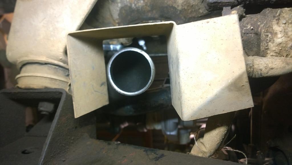
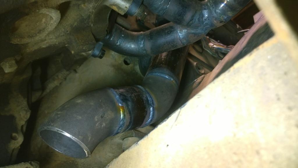
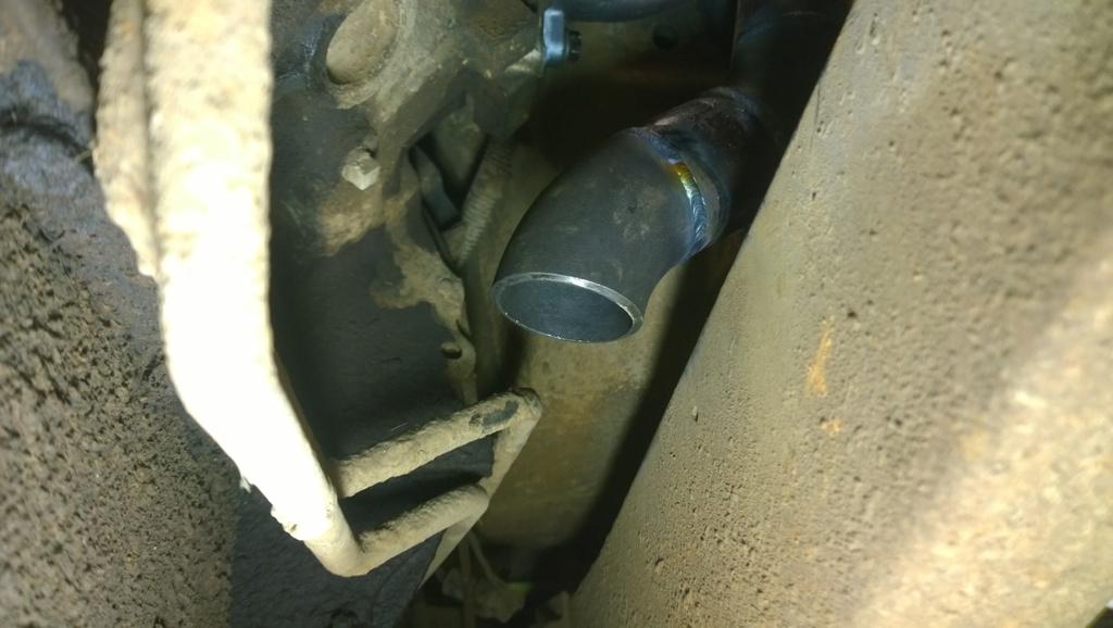
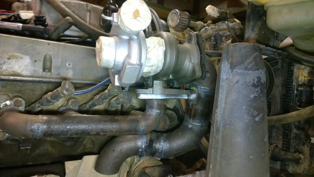
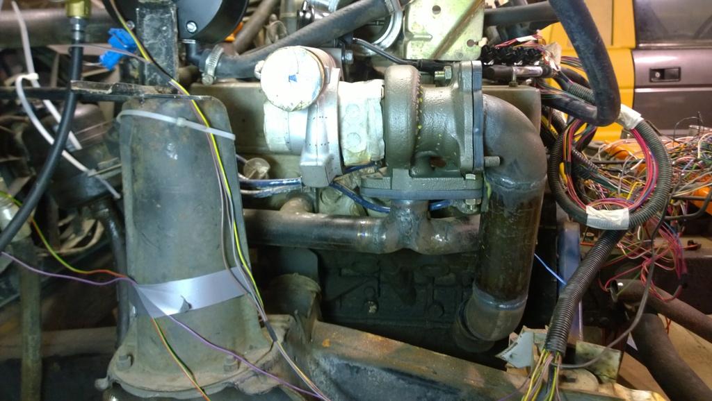
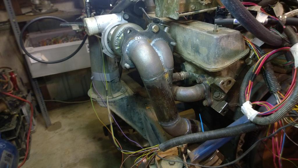
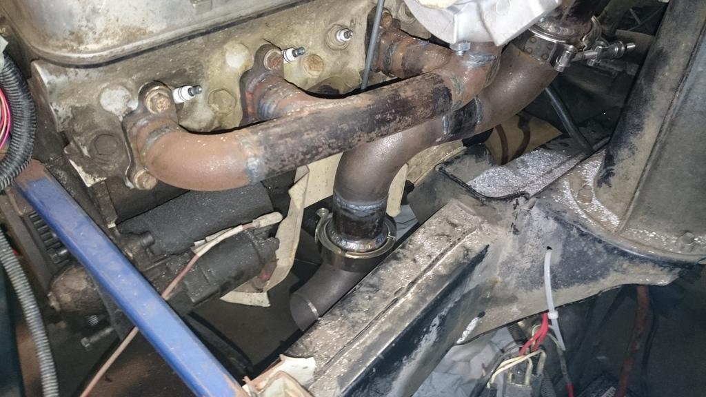
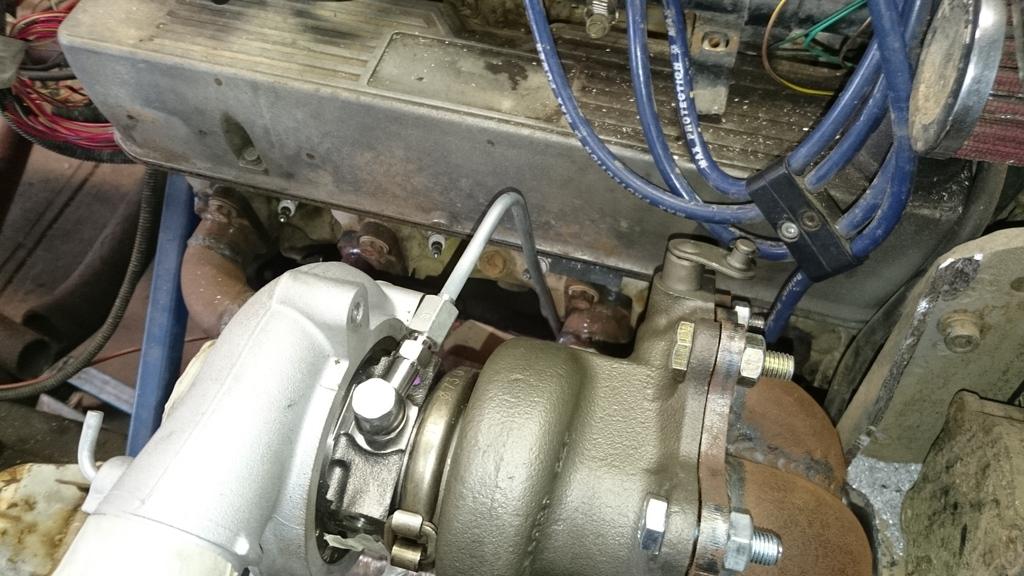
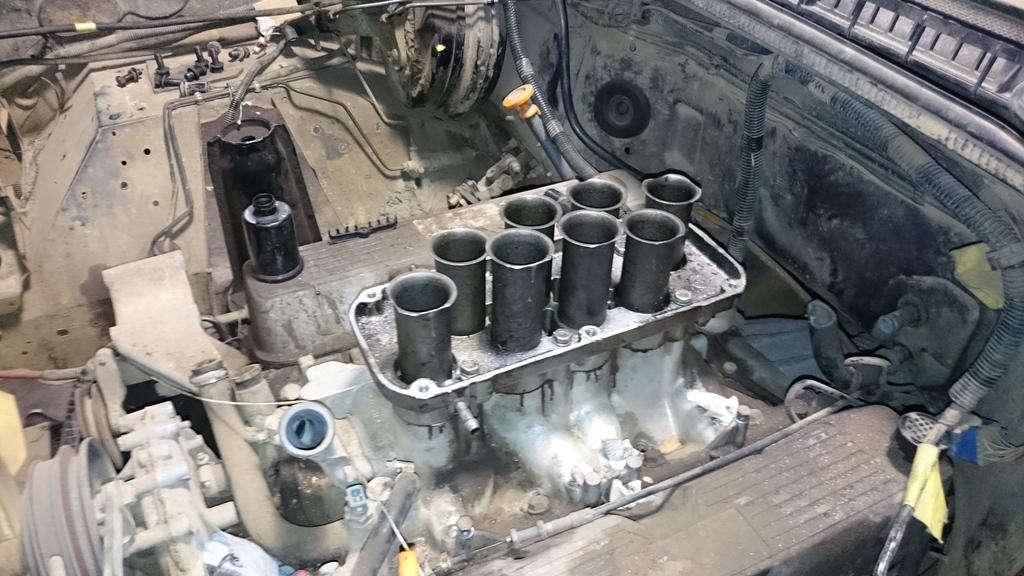
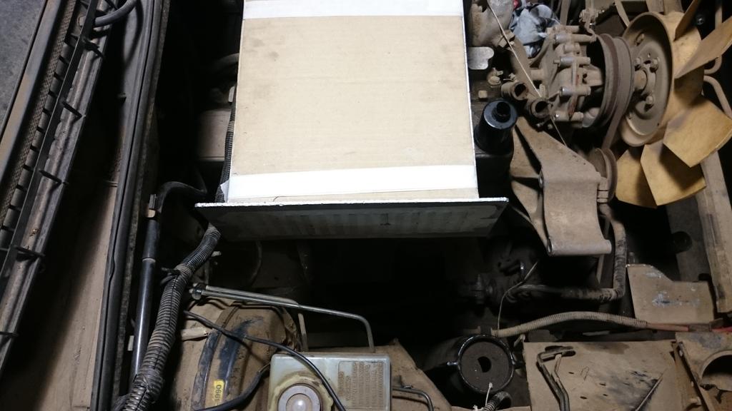
    Re firewall clearance - did you consider (a) penel beating the firewall in (smash it) or (b) cut a section into the fire wall?

    You will need to ensure there is no heat transference otherwise you will have heat or worse issues in the cab - to state the obvious

    89 Orange Rangie UTE - our play thing - sadly now sold
    75 Rangie/Series/Hybrid/LS3 - Bumblebee with a sting!!!!
    2018 RRS - The new touring vehicle - replaces 2012 RRS

  3. #483
    slug_burner is offline TopicToaster Gold Subscriber
    Join Date
    Jul 2007
    Location
    Melbourne
    Posts
    4,024
    Total Downloaded
    0
    Take your oil supply from the filter area, you can use a sandwich plate if you don't already have an outlet available.
    Quote Originally Posted by benji View Post
    ........

    Maybe we're expecting too much out of what really is a smallish motor allready pushing 2 tonnes. Just because it's a v8 doesn't mean it's powerfull.

    One answer REV IT BABY REV IT!!!

  4. #484
    Join Date
    Jun 2007
    Location
    Oatley, NSW
    Posts
    974
    Total Downloaded
    0
    So I haven't had a chance to post up an update for a few weeks. Things have been too hectic. A trip up to QLD for Easter and then this week I was away in Indonesia & Singapore. No progress this weekend, but I figured I should at least post up the progress from the previous weeks.

    Regarding the oil supply for the turbos, I will bow to the opinion of well... everyone... and get the the oil from the outlet of the oil filter. I will run 1/4" hard line to each locations. It will look neater than braided hose running around everywhere.

    Anyway, as for actual progress.

    Because the intake manifold will be under pressure from the turbos, I needed to come up with some way to hold in the LPG injector nozzles from popping out. This is what I came up with and I think it will work perfectly well. Plus it looks reasonably neat (in my opinion).


    I got AN to Banjo adaptors to allow me to hook the oil supply and drain to the turbos. Unfortunately AN uses a 37deg taper where as almost all other taper fittings are 45deg. Because of this 37deg pipe flare tools are expensive. So, I'm going to take a punt and see if the steel pipe flared at 45deg will seal. My gut feel is that it will. Below was a quick trial with a small piece of the 1/4" steel pipe which will form the oil supply line to the turbo. The drain will be a flexible line since it is a larger bore and will be too hard for me to bend.


    This is what it all roughly looks like including the water water supply & drain fittings.


    The channel clamps came in for the turbo dump pipes.


    I only had enough time to fit one on the right hand side last weekend. It wasn't the easiest thing in the world since the welding deforms the machined mating faces. All up I think I will have two clamps on the right hand side dump pipe and only one on the left hand side. That should let me be able to pull everything apart when it is in the car.


    It's all a VERY tight fit. Though I tested it and it is possible to get the clamp off even with this little space available between the pipe and the compressor bracket.
    Stirling

  5. #485
    Join Date
    Jun 2007
    Location
    Oatley, NSW
    Posts
    974
    Total Downloaded
    0
    So we have cracked the 100,000 views on this thread!!! Not quite sure what to make of it though?!? Probably that I am taking too long to get this car up and running!!

    Anyway, again a few more hours spent in the workshop this weekend.

    I got some of the intake parts back from laser cutting (finally). Unfortunately I quickly found that I was a little bit too ambitious with the inside dimensions of the plenum flange.


    With a little bit of cutting, it was all sorted. I then cut and inserted with thread locker studs into the intake manifold. All looked pretty good with the trial fitment.


    I also checked the flange for the throttle bodies and it looked good also, but I didn't have the M6 all thread available so putting in the studs will need to come later.


    I welded up the next joint on the RH down pipe which finished off that side. I'll leave an exhaust shop to finish the run from the end of the elbow.


    Finally, I bent up and terminated the RH turbo oil line in 1/4" steel pipe. I was able to do the whole run in a single piece which was nice. It won't be so straight forward getting to the LH turbo all the way on the other side of the engine!!


    That's it for the week! Till next week.
    Stirling

  6. #486
    Join Date
    Jun 2007
    Location
    Oatley, NSW
    Posts
    974
    Total Downloaded
    0
    Righto, a quick update on some progress:
    The flanges for the Vectra throttle bodies were drilled, tapped and had the studs fitted. So they are ready to go:


    I got the partially welded up Plenum. Unfortunately the guy doing the welding took a few creative liberties. The biggest one being that despite my drawing illustrating that I wanted the box to be welded on flush to the opening of the flange, they went ahead and welded in the 3mm plate on the INSIDE of the flange. So I've effectively lost 6mm and can't fit the assembly over the trumpets...


    So I've now got no choice but to shave off 3mm from all the trumpets to allow the assembly to go on. A compromise I really didn't want. But in hind sight what I may end up doing is removing the trumpets away. That is of course if I am happy with the amount of torque that I will get with shorter intake runners. I'll save that for when the car is actually running!


    And this is where you realise how BIG this plenum assembly actually is! I'm going to be needing to do some serious bonnet modifications later!!


    This is the only area I needed to look at carefully, the angled transition needs to make sure it doesn't foul with the brake master or the brake lines, so I took some measurements in this area. Unfortunately it means that I will need to make the RH transition 40deg off centre which isn't ideal, but I don't have much choice!


    Oh and the latest news is that the 4HP22 auto box with the 4HP24 internals will be ready by the end of this week! I'm going to have to order the engine soon!

    That's it for tonight!
    Stirling

  7. #487
    Join Date
    Apr 2012
    Location
    Orange, NSW
    Posts
    7,965
    Total Downloaded
    0
    I understand about 4 or 5 of the engineering/automotive related words in your posts.
    But damn it's cool
    Keep it up!
    The Phantom - Oslo Blue 2001 Td5 SE.
    Half dead but will live again!

    Nina - Chawton White 2003 Td5 S
    Slowly being improved

    Quote Originally Posted by Judo View Post
    You worry me sometimes Muppet!!


  8. #488
    slug_burner is offline TopicToaster Gold Subscriber
    Join Date
    Jul 2007
    Location
    Melbourne
    Posts
    4,024
    Total Downloaded
    0
    If it's not done iaw the drawing you don't have to take it! Is it a paid job or a love job?

    I suspect that you could arrange the charge coolers at a slight angle to use the space above the rocker covers and the flanges on the charge coolers are not required as you have a welded assembly.

    I think it will be easier to get the brake lines re routed to give you maximum space for your turbo pipe work.

    Looks like fun.
    Quote Originally Posted by benji View Post
    ........

    Maybe we're expecting too much out of what really is a smallish motor allready pushing 2 tonnes. Just because it's a v8 doesn't mean it's powerfull.

    One answer REV IT BABY REV IT!!!

  9. #489
    Join Date
    Jan 1970
    Location
    Gold Coast
    Posts
    1,938
    Total Downloaded
    0
    I agree with slugburner getting new brake lines made and rerouted is the easier option and you might need that space anyway to service the new parts on top

    Brake pipe is easy to bend and route. You just need to make up the pipe you want with lengths and bends (either with a tool or by hand) then get the ends done at a brake shop (unless you have your own tool)

    This one is dead easy to use, fairly cheap and works perfectly on steel pipe
    Austin Rover Hand Held on Car or Bench 3 16" Brake Pipe Line Flaring Tool Kit | eBay

    Before I got one of these tools I used to get my local shop to add the fittings based on my measurement using a length of string - I then bent them to fit the engine bay.

    89 Orange Rangie UTE - our play thing - sadly now sold
    75 Rangie/Series/Hybrid/LS3 - Bumblebee with a sting!!!!
    2018 RRS - The new touring vehicle - replaces 2012 RRS

  10. #490
    Join Date
    Jun 2007
    Location
    Oatley, NSW
    Posts
    974
    Total Downloaded
    0
    Thanks for the input guys. I will probably need to do some minor modifications to the brake lines leaving the master cylinder but either way I need to leave a little bit of space between the intake assembly and the master cylinder to fit your hand through!

    I did another 6 or so hours in the workshop today, below is the progress.

    The oil line for the LH turbo was bent up. I needed to do it out of two runs with a double union compression fitting half way. Below is how it all fits up on the test engine.


    I welded on the bottom V-clamp and elbow to the RH turbo dump pipe. I have one V-clamp left over which was intended to be placed just down stream of where the waste gate pipe joins the main dump pipe for easier disassembly. But I think I can get away with just having the one on the bottom.


    I also did the ambitious thing of welding in the turbo oil drain nipples onto the sump insitu. That was a whole world of pain due to not being able to get my head into a position where I could see!! Anyway I eventually got there after blowing only one hole into the sump! Lucky I have a spare sump pan. When the final engine build goes together I'll do any tidying up that is necessary at that point. For the purposes of the test engine, this is sufficient.


    As I've typed this I've just realised I forgot to get the measurement of the pipe lengths required to run the drain down to the sump! I guess I'm going to have to dash back to the workshop tomorrow!

    One other thing I have done this evening is create a couple designs of a heat insulator strip which I will fit in two locations. One 5mm heat insulator between the intake manifold and the plenum trumpet base and another 5mm heat insulator between the plenum trumpet base and the plenum cover. Since I am mounting the intercooler cores directly onto the plenum I need to limit as much heat from the engine being conducted through the aluminum because the intercoolers would work as very efficient air heaters! below is the model of the intake to plenum base insulator.


    I'm even toying with the idea of cutting off the water coolant runners and thermostat housing which is cast onto the front of the intake manifold and welding up a separate assembly. The amount of heat that would be soaking from the hot water leaving the heads into the intake manifold would be ridiculous. Anyway, I will save that ambitious task for sometime in the future when the car is actually on the road!

    With regards to the heat insulators, if anyone wants to buy some PM me because I will be arranging for some to be made in the coming weeks. If you want to understand what benefit there is in insulating intake components, have a read of this excellent article written for a Mazda V6:

    AutoSpeed - Cool Stuff - Manifold Insulators

    Till next time.
    Stirling

Page 49 of 82 FirstFirst ... 39474849505159 ... LastLast

Bookmarks

Bookmarks

Posting Permissions

  • You may not post new threads
  • You may not post replies
  • You may not post attachments
  • You may not edit your posts
  •  
Search AULRO.com ONLY!
Search All the Web!