-
17th February 2010, 02:17 PM
#101
[QUOTE=justinc;1141546]Mike,
Best advice I can give you is Don't skimp on tyres,(Get rid of those ST's before you go ) or suspension. Learn as much about that simple little engine as you can, oil and filter changing and tappet adjustments, timing belt and oils brake fluid and cooling system service before you go, and that should be all you need
")
Good thing you HAVEN'T got all that $$$ to splash out at ARB etc, it'll only add more weight to the vehicle and look you got THIS far without it all...
check out the march 10 edition of landrovers international, there is an article on a bog standard 200tdi disco thats has been around the world three times!
-
16th March 2010, 11:39 AM
#102
I'm back again, and despite apeparances I have been busy this past couple of weeks It had to happen sooner or later - the electronics had to get a good seeing to, and, as it turned out, a good overhaul.
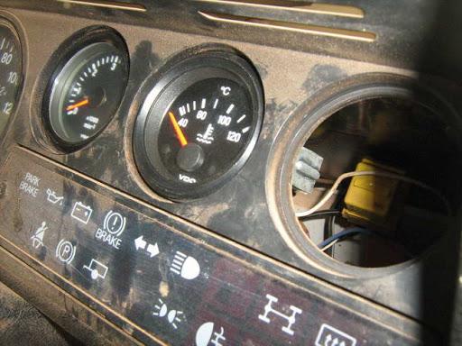
It started out pretty straightforward - the stock standard temperature gauge in the Defender is a very binary "it's cold/it's boiling hot" design, and seeing as I had a VDO equivalent lying around in the shed, it was an easy upgrade.
New Gauge in the console:
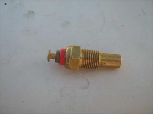
And a new temperature sender to match:
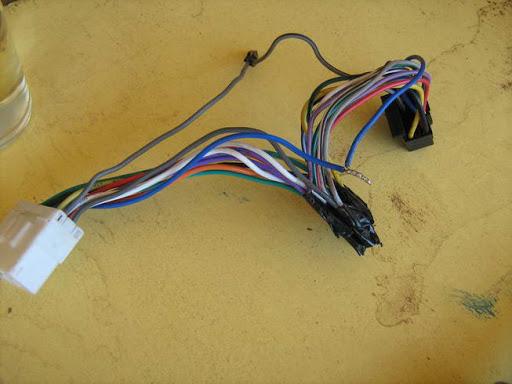
There'll be an oil pressure gauge going in the dash in the future, therefore I'll be moving the fuel gauges for both the main and auxiliary tanks out into the centre console. Leads need to be extended....
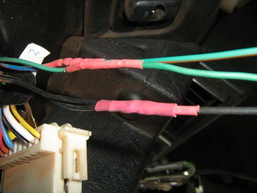
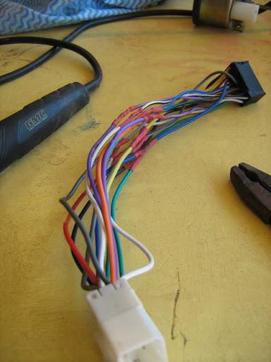
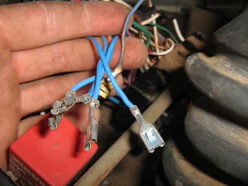
I have to admit, one thing I hate is shoddy electrical work - maybe it's the electrician or engineer in me, but connections like this one make me cringe...
10 minutes with the soldering iron and heatshrink, and it's much better....
It's already beginning to get messy (you should see it now...)
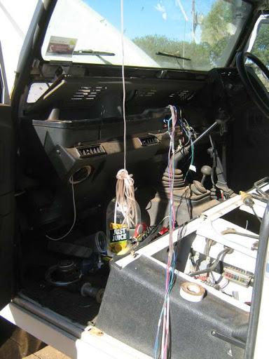
In this case, it's only the connection for the back of the radio, so worst case scenario I end up with no tunes, or constant static. But as you will see next, the potential can be much worse....
-
16th March 2010, 12:39 PM
#103
HEADLIGHT RELAY UPGRADE
I've always had issues with the Defender's lights - at best they looked like a candle in a jam jar - dim, yellow, and more or less useless, and had decided long ago that it needed to be upgraded to a relay driven system. For the non technical out there, what this means is that instead of the power for the lights running through the fuse board, switch, and half a mile of shoddy cable, instead the power for the lights comes directly from the battery through heavy gauge cable, and is switched on and off by a relay. In effect, the lights get the maximum power available to them, and burn brighter.
I took a few measurements before I started, and the results were pretty shocking:
Voltage at the battery: 13.2 V
Voltage at the lights: 9.75V
To put that into perspective - normal engine-running voltage in a "12-volt" automotive electrical system is around 13.5 volts. At this voltage, halogen headlamp bulbs achieve 100 percent of their design luminous output. When operating voltage drops to 95 percent (12.825v), headlamp bulbs produce only 83 percent of their rated light output. When voltage drops to 90 percent (12.15v), bulb output is only 67 percent of what it should be. And when voltage drops to 85 percent (11.475v), bulb output is a paltry 53 percent of normal! So 9.75v was only giving me a fraction of the light available to me.
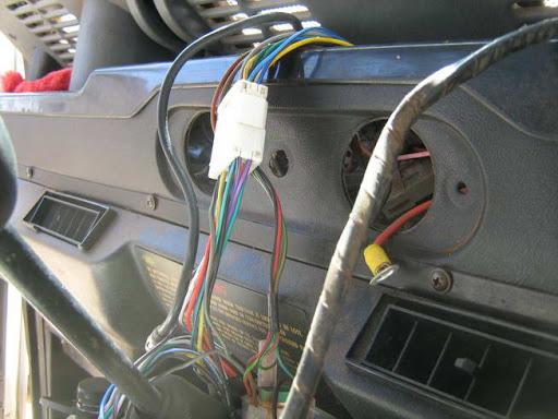
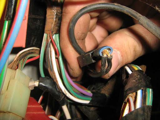
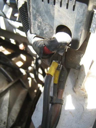
A look behind the fuseboard revealed more horrors - someone had made an attempt to upgrade the lights before me, couldn't figure it out, and tucked the leads back in.... without insulation...
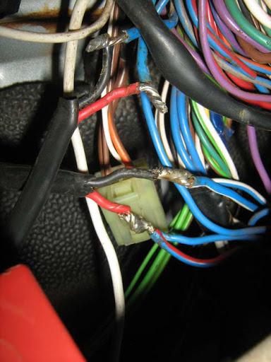
Another example of shoddy work - this time the auto electrician that fitted the immobiliser for the previous owner. That's the live straight into the ignition barrel, and if that shorts out....
Anyhow, on to the upgrade.
This is a basic diagram of how the lights will be upgraded.
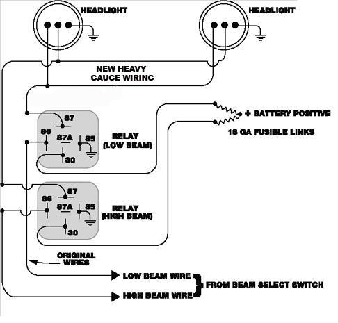
As you can see from the diagram, the existing wiring is used to drive the relays,while the relays themselves make a direct circuit between the lights and battery when the relay is triggered. I use one relay for dims, one for heads. It is possible to use a single relay with an 87a contact (SPDT switch), but the problem with this is that if you lose the relay, you lose all lights at once.
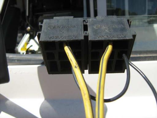
There are many ways of mounting the relays - jaycar sell relay blocks, and many relays come with a screw tab where you bolt the relay directly to the chassis, and use spade connectors to hook it up (messy, unprofessional and easy to confuse the wiring IMHO), but if you are happy to salvage parts, which I am, then the relay blocks that come with older Fords are more than suitable. They are easily mounted, take tagged spade connectors, and are modular, so if you ever need to add an additional relay, it clips on to either side.
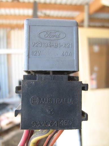
I won't be using the ford relays - I just need the mounting blocks. Instead I'll be using Bosch - they have proven reliability and are easily picked up pretty much anywhere.
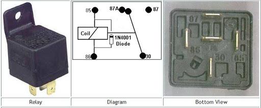
The on the relays are universal terminal designators:
# 86 is the relay switching (control) circuit input.
# 85 is the relay switching (control) circuit ground.
# 30 is the power circuit input.
# 87 is the power circuit output when the relay coil is energized.
#87a is the power circuit output when the relay coil is NOT energized. (not used in our case)
Be aware that the layout of the terminals can change between relays with an 87a terminal, and relays without.
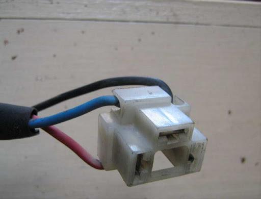
The inputs to drive the relays can be taken from the back of the fuse board. First, cut the Blue/Red wire and extend it - this becomes the input to the Dipped Lights relay. Then, cut the Blue/White wire and extend it - this becomes the input to the Head Lights relay. (Terminal #86)
Terminal #85 on each relay gets connected to ground. At this stage, switching between heads and dims on the dash will activate the appropriate relay - you should be able to hear them clicking in and out.
Power from the relay to the lights (terminal #87) must go through a fuse - I used the existing fuses in the fuse board. To do this you will need crimped connectors with a tag which allows them to lock into place in the fuse board.
Comparison between the old wiring and the heavier, upgraded wiring. The differences are apparent.
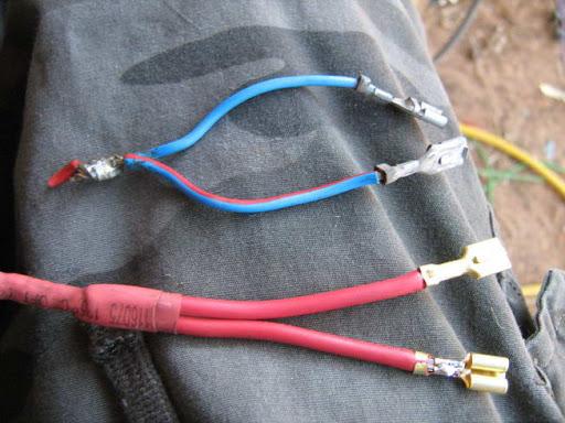
Power from the relay for both heads and dims - the cables are forked, as left and right lights have separate fuses.
The cables running from the fuse board to the lights also needs to be upgraded, otherwise the previous work is pointless. You can make up brand new connectors fro the back of each bulb, but if you want an easier option, nip down to the wreckers yard and find a Volvo - the wiring in these is high quality, heavy gauge, and sealed. I use them as a source of all my wiring, due to the quality of the cable, and the long runs of wire that they have. Grab the wiring from the headlights - the wires will be long enough to run to the fuse board.
Run the cables back along the standard routes:
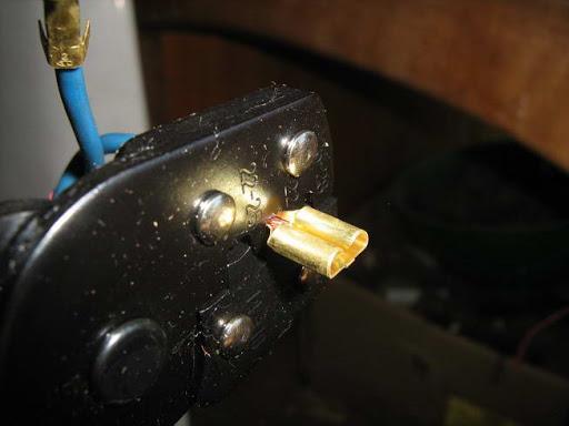
This is what a properly crimped connector should look like...
The original wires from the fuse to the lights can be removed from the back of the fuse board...
...and replaced with the new wiring.

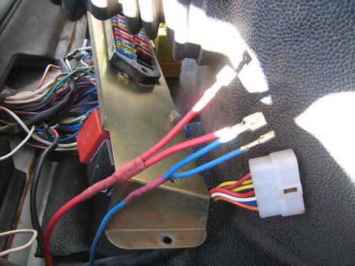
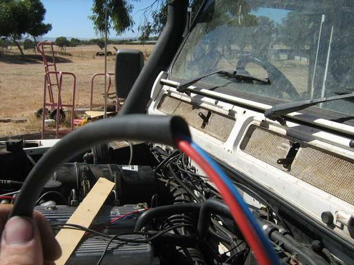
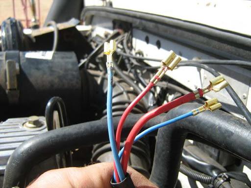
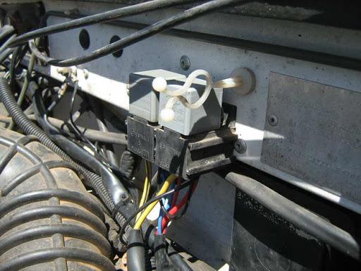
Connections out in the engine bay for the relays:
Thin blue - driver for the dims relay.
Thin red - driver for the heads relay.
Thick blue - Power from dims relay to fuse board (and onto lights).
Thick red - Power from heads relay to fuse board (and onto lights).
(Yes I did notice that the heavy red wire had been pinched, and I replaced it after the photo was taken).
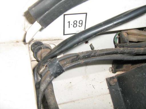
Power from the battery to the relay:
Power can be taken from underneath the fuse block in the engine bay.
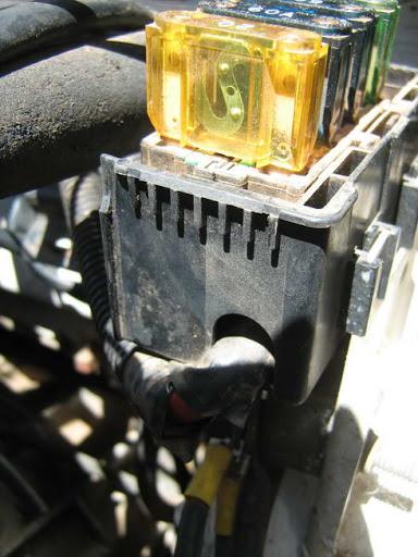
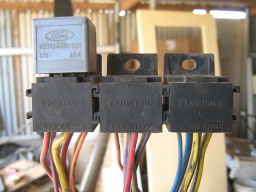
The relays currently in place. Ground for the relay can be taken from the existing earthing bolt in the upper left of the photo.
And that's pretty much it! Connect up the new blocks to the back of the light fittings, start her up, and test out your lights. The lights themselves told the story for me - bright, BRIGHT white, an unbelievable difference in range, but the meter backed me up with figures.
13.1v at the light globe, compared to the previous 9.75v....
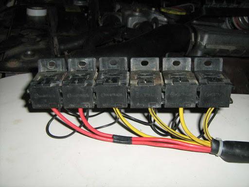
Seeing as this worked out so well, I added relay blocks for the roof lights, front spot lights, and a couple of spares for extras later...
Hope this helps. Any questions, I'm glad to help.
-
16th March 2010, 01:05 PM
#104
Nice work. Following this with interest.
-
16th March 2010, 01:22 PM
#105
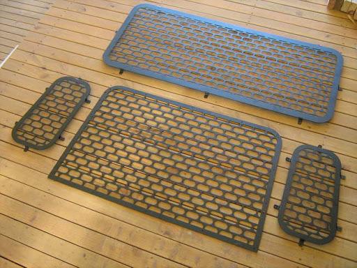
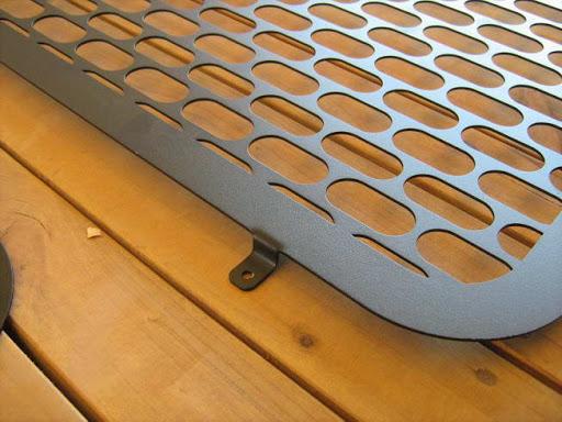
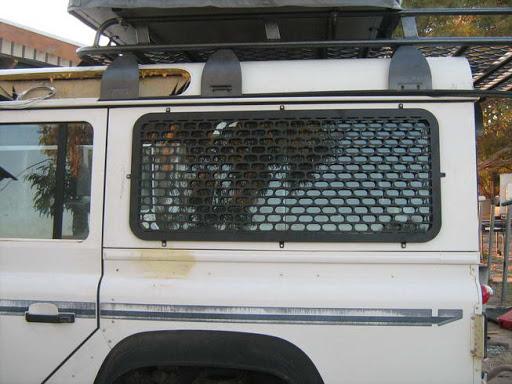
After a bitof a wait, the window guards are complete, and if I do say so myself, thy look pretty amazing.
I posted some photos in a previous post of the cut out guards, naked and in all their glory, and since then they have taken a trip to the powercoaters to be blasted, powder primed and powdercoated in satin black. Some phone calls led me to Brian of Adelaide Powder Coaters, and at risk of sounding like I'm pimping his business, he couldn't have been mroe helpful, and I'll certainly be using his services again.
The full set - I only have need for one side window, but for those interested later, they'll come in sets of two.
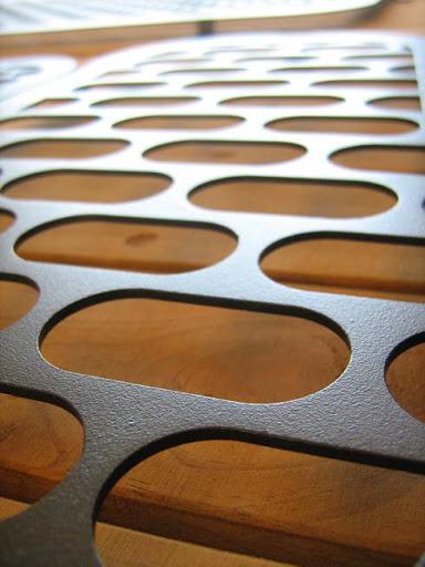
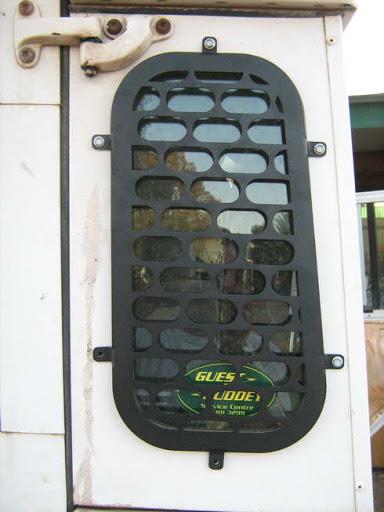
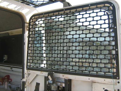
The back window guard:
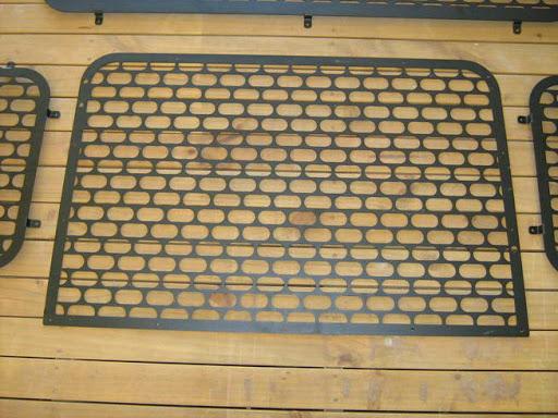
And to give an idea of the quality of the powder coating:
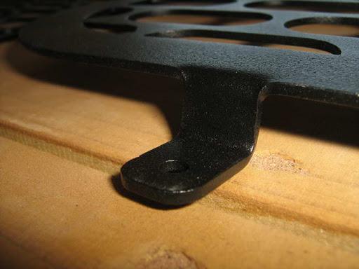
Mounting them is pretty straightforward. Line up the guards over the window, mark out the positions of the tabs, and drill...
The backwindow guard mounts on the inside due to the wiper.
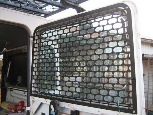
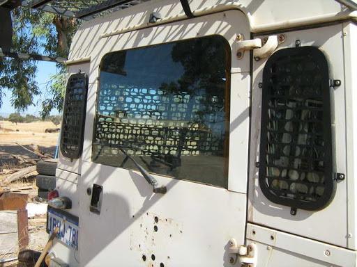
The back windows, temporarily mounted with tec-screws to make sure it all lines up (this was the first set of guards I made)
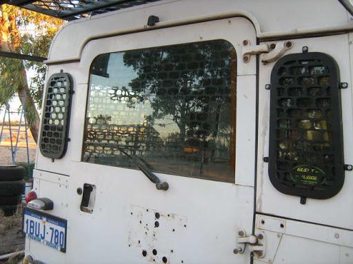
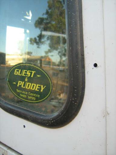
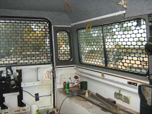
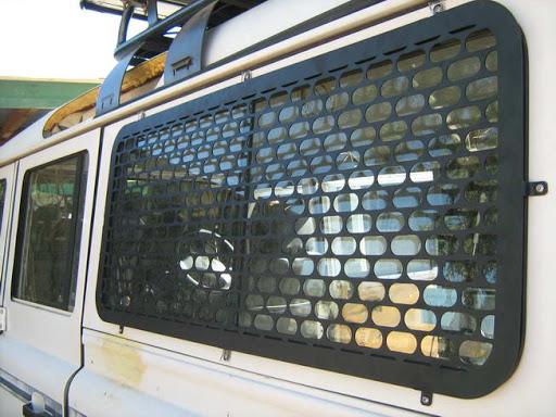
The side window guards, temporarily mounted:
A quick look from the inside (sorry about the mess)
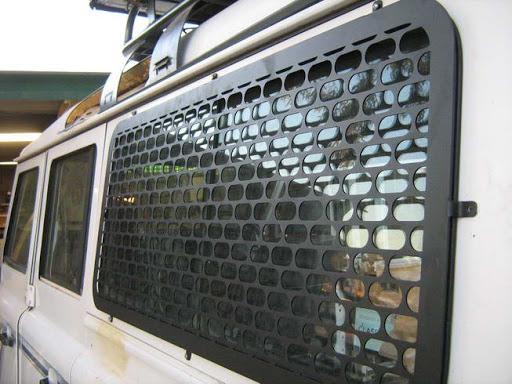
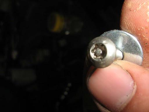
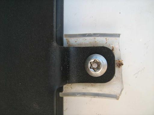
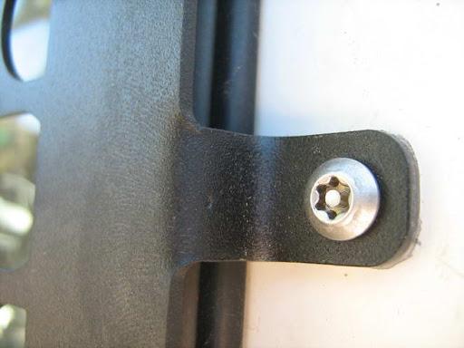
The guards are designed to be rivetted on, but I used secuirty bolts toprovide me with the option of removing them. I used nnyloc nuts on the inside, because even if someone does come along with the gorrect bit (unlikely), once the nyloc nut loses grip on the body, the bolt will just spin without loosening.
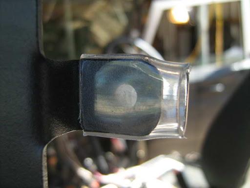
The powdercoating should provide an insulating barrier between the steelguards and the aluminium body, but if you are really concerned, I used some piping as a barrier...
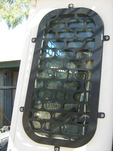
The guards, permanently mounted:
-
19th April 2010, 07:52 AM
#106
Any more news on the build up??
Adam
-
30th April 2010, 09:07 PM
#107
Mike so how's it going
-
3rd May 2010, 02:17 PM
#108
-
10th May 2010, 11:28 AM
#109
Sooooooooooo
is Mike still with us and did the screens ever go ahead
-
12th May 2010, 01:22 PM
#110
Mike,fascinating report on the prep of your vehicle.Good idea to cover the roof foam with ply,because if it is anything like I had on the roof of a lwb series 2a it went like the original foam ie crumbly.You should consider replacing the black coolant tank with a white one because, sure as night follows day, it will leak from the seam!Cheaper to get from the UK.
 Posting Permissions
- You may not post new threads
- You may not post replies
- You may not post attachments
- You may not edit your posts
-
Forum Rules
Search AULRO.com ONLY!
|
Search All the Web!
|


 Reply With Quote
Bookmarks