Page 1 of 2 12 LastLast
Results 1 to 10 of 14

Thread: Front and rear recovery points - bolt sizes

  1. #1
    Join Date
    Feb 2009
    Location
    Pretoria, RSA
    Posts
    536
    Total Downloaded
    0

    Front and rear recovery points - bolt sizes

    Attached are the recovery points I added to my D2.
    What bothers me is that the std bolt size is 10mm.
    I used grade 12.9 allen cap bolts but my structural engineer at work recommended that I use bigger bolts.The bolts closest to the eye will see about double the load of the eye and the outside bolt about the same.
    The lug itself is made of steel with yield of 300Mpa.
    Bellow is a link to a simmlar lug.
    Any comments suggestions or reccomendations.
    I saw a lot of stress diagrams in the "Rear recovery point" thread.
    I added this lug to both the front sides and left rear.
    Right rear will take longer as I will have to remove extra tank to get bolts in.

    http://www.aulro.com/afvb/technical-...ery-point.html


  2. #2
    Join Date
    Sep 2007
    Location
    Kiwiland
    Posts
    7,246
    Total Downloaded
    0
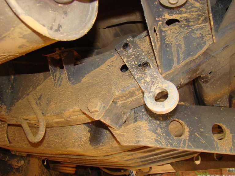
    I'd definitely go for bigger bolts, I'd also align them if possible more in the direction of the pull.

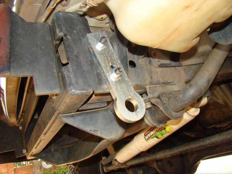
    IMO 2xM12's are the minimum, for loading like yours you want 3 or 4 M12 bolts. Are those M8 or M10?

    The other issue is clamp load. Bolts shouldn't take shear themselves, they should be done up tight enough that friction between the two surfaces they are clamping together takes the load.
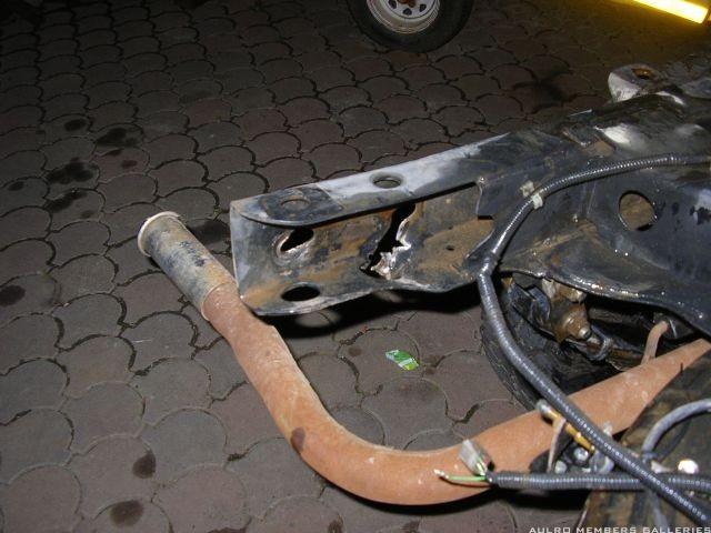
    To acheive this across a chassis section requires crush tubes to be welded in. Crush tubes suitable to support a fully torqued M12 grade 8.8 bolt need to be at least 22mm diameter since they have a 13mm hole through them.
    Bigger if you're using higher strength bolts torqued up tighter.

  3. #3
    Join Date
    Feb 2009
    Location
    Pretoria, RSA
    Posts
    536
    Total Downloaded
    0
    To get a friction grip connection on a chassis is a bit af a bummer.
    Fro a true friction grip connection the surfaces should be bare metal.
    There are already crush tube at these holes and made for M10 bolts.
    The STD front bumper mounting bolts.
    The rear is already being altered but the front stay a problem.

  4. #4
    Join Date
    Sep 2007
    Location
    Kiwiland
    Posts
    7,246
    Total Downloaded
    0
    Quote Originally Posted by Rudolf View Post
    To get a friction grip connection on a chassis is a bit af a bummer.
    Fro a true friction grip connection the surfaces should be bare metal.
    There are already crush tube at these holes and made for M10 bolts.
    The STD front bumper mounting bolts.
    The rear is already being altered but the front stay a problem.
    That swaybar location gives you a lot fewer options than on a D1/RRC etc. I have a hook on my RRC with the bolts drilled up through. No crush tubes yet because I need to take the front of the body apart to do it properly. I plan to add a flat plate with a shackle eye to the other side when I finally do it properly.
    In the mean time i risk ovalising the holes if I pull too hard.

  5. #5
    Join Date
    Feb 2009
    Location
    Pretoria, RSA
    Posts
    536
    Total Downloaded
    0
    Oval holes is another warning I got from our resident engineer.
    The chassis tubes wall thickness is not enough and could deform with small diameter bolts.
    Justifies goin the friction grip route with a minimum of m12 bolts.
    For design pusposes I would still design it for shear only.

  6. #6
    Join Date
    Feb 2009
    Location
    Pretoria, RSA
    Posts
    536
    Total Downloaded
    0
    Here is a recovery point gone wrong.
    Four bolts, looks like M12.
    Chassis frame had no stiffeners or doubler plates.
    Oh, by the way. This is from a Toyota Hilux.
    The lug did not come off but damadged to chassis and body work.


  7. #7
    Join Date
    Sep 2007
    Location
    Kiwiland
    Posts
    7,246
    Total Downloaded
    0
    That's ugly.
    I'm currently doing some head scratching to fit a decent recovery point to a mates bighorn (jackaroo). the chassis rail on that is completely boxed in, maybe 2.5mm wall and has M12 captured nuts inside.
    The nuts will just pull through the 2.5mm rail if anything serious happens but to get something decent in there will require cutting open the rail and welding some decent anchors in.

    I think a lot of bodywork needs moved to even be able to do that. But interestingly enough, if you just bolt a 4500kg rated hook with M12 grade 8.8 bolts then most 4wd clubs will deem it okay.

  8. #8
    Join Date
    Feb 2009
    Location
    Pretoria, RSA
    Posts
    536
    Total Downloaded
    0
    Another theory for bolts sizing.
    Recovery points are mostly loaded at a angle.
    This does no good for a strict friction grip connection.
    Rather design the connection for a load combination.
    The bolts should be able to handle both shear and tension.
    For the friction grip design 8.8 bolts should not be used.
    Rather use 8.8S or 10.9S bolts and torque them to spec.
    These bolts should never be reused once torqued.
    Again for friction grip the chassis rails are too thin and would not stay flat.
    A doubler plate of min. 6mm should be welded on for a better flat surface.

  9. #9
    Join Date
    Feb 2009
    Location
    Pretoria, RSA
    Posts
    536
    Total Downloaded
    0
    Some reading I found at a local site about recovery point design and a local 4x4 forum.

    Vehicle Recovery Points And some technical aspects, by Mike Lauterbach
    [ame=http://www.4x4community.co.za/forum/showthread.php't=18913]Recovery Point Disco TD5 - SA 4x4 Community Forum - The only forum for the offroad and 4x4 enthusiast[/ame]

  10. #10
    Join Date
    Sep 2007
    Location
    Kiwiland
    Posts
    7,246
    Total Downloaded
    0
    Quote Originally Posted by Rudolf View Post
    Another theory for bolts sizing.
    Recovery points are mostly loaded at a angle.
    This does no good for a strict friction grip connection.
    Rather design the connection for a load combination.
    The bolts should be able to handle both shear and tension.
    For the friction grip design 8.8 bolts should not be used.
    Rather use 8.8S or 10.9S bolts and torque them to spec.
    These bolts should never be reused once torqued.
    Again for friction grip the chassis rails are too thin and would not stay flat.
    A doubler plate of min. 6mm should be welded on for a better flat surface.
    I agree that recovery points are mostly loaded at angles. But the bolt effects on this are primarily the result of attachment geometry rather than applied load. So you need a bolting solution engineered for each individual case.
    You can get dry friction of roughly 0.3 time the clamp load, AS3990 states externally applied tension shouldn't be more than 0.6 times the clamp load.

    Presuming the 8.8S grade you mention is also known as HSFG? I don't see any real advantage over normal grade 8.8 for this application.

    But a 6mm doubler won't give you the clamp load you need, it will help spread the recovery forces along the chassis.
    You need crush tubes and big ones.
    For M12 grade 8.8 torqued to yield you're resisting 5.3 ton per bolt. This needs a mild steel crush tube with at least 240mm^2.
    For M12 grade 10.9 torqued to yield it's 340mm^2 resisting 7.4 ton per bolt.

    Basically 25mm crush tubes with a 13mm hole through them are the minimum.
    Last edited by Dougal; 20th June 2009 at 08:23 AM. Reason: clarification

Page 1 of 2 12 LastLast

Bookmarks

Bookmarks

Posting Permissions

  • You may not post new threads
  • You may not post replies
  • You may not post attachments
  • You may not edit your posts
  •  
Search AULRO.com ONLY!
Search All the Web!