

 Reply With Quote
Looks like he used the fog light circuit to power the controller hence the bigger fuse, he might have modified the process afterwards as per the guide he posted.

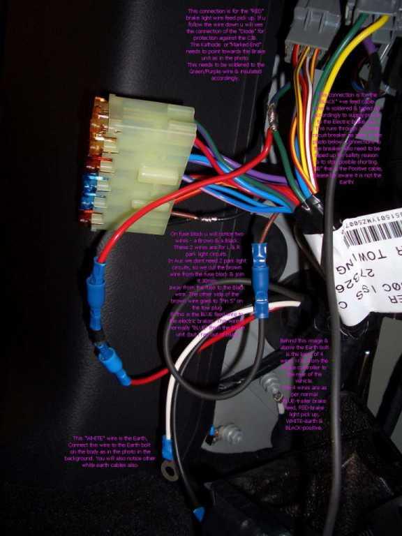
Thanks. Here's a photo of my rear fuse block and wiring. My brake controller was installed by Peter "Sniegy" at Landrover Melbourne when I bought the car new in 2009. It is appears as though the Fog lamp fuse (fourth fuse down in the block) was changed to a 20amp fuse. This fog lamp fuse is normally just a 7.5 amp. This 20amp fuse has broken twice before during a braking event in the last year and the hydraulic brakes on the trailer remain clamped on as a result - a danger and major inconvenience.Originally Posted by loanrangie

I would like to have my wiring checked. Is there a specialist Landrover Auto Electrician that anyone can recommend in Melbourne?
Regards,
Paul
 LordRover
Subscriber
LordRover
SubscriberLooks like he used the fog light circuit to power the controller hence the bigger fuse, he might have modified the process afterwards as per the guide he posted.
MY08 TDV6 SE D3- permagrin ooh yeah
2004 Jayco Freedom tin tent
1998 Triumph Daytona T595
1974 VW Kombi bus
1958 Holden FC special sedan
Member
how do i wire up a tekosha brake cotroller the pictures do not show the location of the fuse box etc
Master
SupporterHi Folks,
informative thread.
I am hoping to get a van later in the year and will require EBC to be fitted. The van in mind has mandatory flat 12 pin as well as anderson plug to keep van battery topped up for the breakaway system.
Intent will be to fit a dedicated flat 12 pin socket to the D3 as well as the anderson plug.
To try and summarise to see if I am understanding this correctly.
- +ve from battery via 30A auto reset CB then to black wire to ECB
- -ve from negative terminal of battery or should it be from the chassis post? Then to WHITE wire to ECB
- From ECB trailer brake wire BLUE direct to the flat 12 pin plug (don't see the need to splice into existing trailer harness as I won't be using the 12N socket for the van)
- Diode connection: from trailer plug brake light wire to diode Cathode, diode Anode then to green/purple wire which is vehicle brake light wire. EBC RED trailer brake light wire comes from diode Cathode. This bit I am not sure about is where to make that connection. I was not able to zoom in with any clarity on the original photo.
- Other trailer light functions for indicators, side / rear lights splice into existing trailer plug harness.
do I have this correct?
Mud map schematic
EBC cct.jpg
thanks for bearing with me.
cheers
Peter
ChatterBox
SubscriberAs per Sniegy’s original post you will find the higher resolution version of his hard to read photo in his members gallery.
Need to open link below from a browser window like chrome.
Message - AULRO Photo Gallery
Still hard to read the purple text but if you click on the picture to open and then zoom in it is almost all readable.
Master
Supporterthanks mate, much appreciated, I can now just read it.
There were comments up further in the thread from another member and Sniegy about putting the diode further downstream to also pick up the trailer, wasn't sure where he meant by that. Anyway I will figure it out when the time comes.
cheers
Peter
ChatterBox
SubscriberIn reality the original photo and write up is no longer applicable as the set up changed almost totally from the way Sniegy first would wire things up.
Your summary is probably the most concise re-write up.
This picture from midway through the thread is probably the clearest diagram for where to add the diode:

Master
SupporterThese diagrams further illustrate what needs to be done and can be found in the Redarc manual.
wiring 1.jpg
wiring 2.jpg
 Posting Permissions
| Search AULRO.com ONLY! |
Search All the Web! |
|---|
|
|
|

")
")
Bookmarks