

 Reply With Quote
Well what would you like to know?
(after you've read the FAQ and searched and not found the answers...)

Evening Gents
Purnell in Blakehurst Syd. Now i am getting confused. I pick up my Caravan in a few weeks and need to get this sorted.
Any more info would be nice.
Cheers guys
 Moderator
Well what would you like to know?
(after you've read the FAQ and searched and not found the answers...)
ChatterBox
As Rob said Paul, Ask away, i am not too clear what info you require.
The D4 will require the LED module to get things like the Trailer assit to work properly when the trailer is connected (as it will adjust the oscillations)as all the Discovery 4 models come with Trailer assist.
Also for the rear park assist to work(or stop working when the trailer is connected).
HTH.
Cheers.
Swaggie
Where's the symbol? My trailer has incandescent globes and I haven't seen any extra indications.Originally Posted by roamer

MY21.5 L405 D350 Vogue SE with 19s. Produce LLAMS for LR/RR, Jeep GC/Dodge Ram
VK2HFG and APRS W1 digi, RTK base station using LoRa
Master
Little green trailer symbol comes on when blinkers flash.in tacho screen
Master
Hi Sniegy,
I'm new to this forum. I'm picking up a D4 (hopefully) in June and will need a brake controller and most likely an LED module fitted. In one of your replies you indicate that you do this.
Where abouts in Melbourne are you and how do I get in touch with you? Also, there's a Prodigy P3 on fleabay for $169 - is it worth getting this do you reckon?
Thanks
Watpub
ChatterBox
Hi Watpub,
I actually work for a dealer in Melbourne. (MLR).
Not sure where you are picking up your vehicle from, but either way i can organise one or both components you require.
Work email is psnieg@mlr.com.au if you require any further info. or just PM me here.
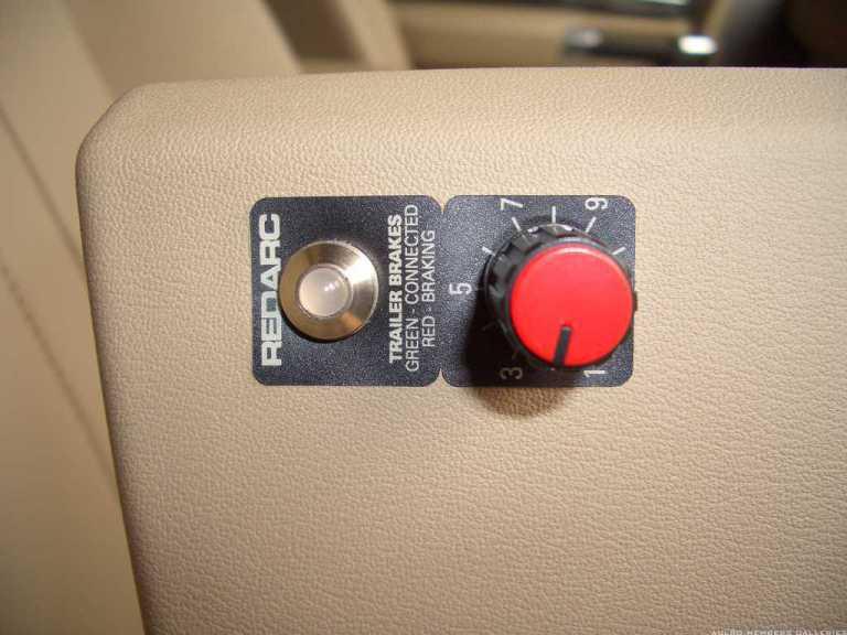
The Electric brake units are a personal thing, i have a RedArc Remote head in mine & love it. But each to there own.
The P3 prodigy some people swear by & other dont like them...Its just like tyres...
Cheers.
ChatterBox
I thought i would clean up a few of the not-so-good photo's.
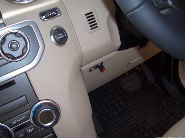
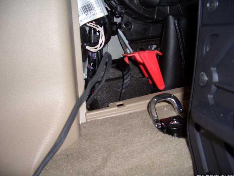
So this is my vehicle i have fitted a Red Arc remote head trailer brake unit.
Principle is the same as the original post, but with a few tips i have added to help those who wish to tackle this job.
I could of mounted the LED & Switch/Dial vertical, but actually prefered it this way.
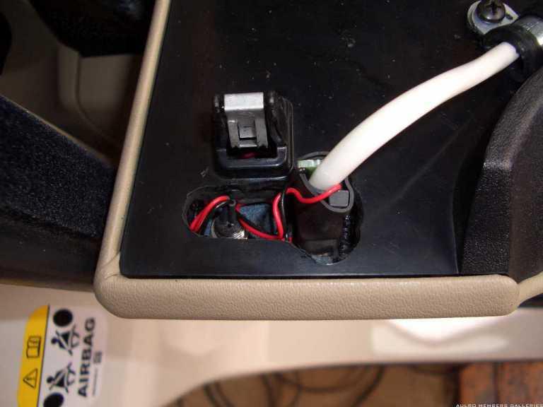
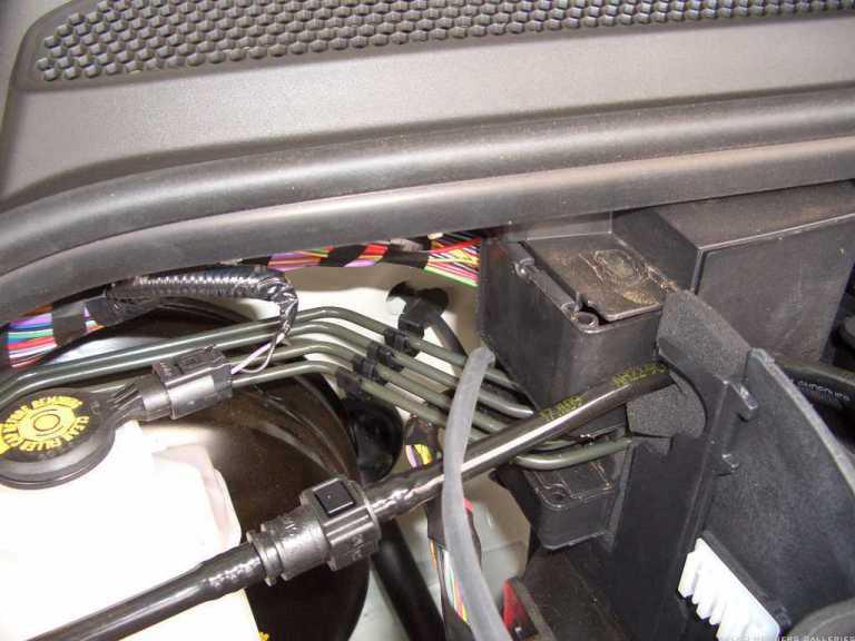
As you can see from the photo below the cover is a honeycomb design, therefore allowing a die grinder & some patience to go to work.
I pushed a screwdriver through the insulation from the engine bat so i could run the cables. Just a not the firewall is double skinned as you can see in the photo.
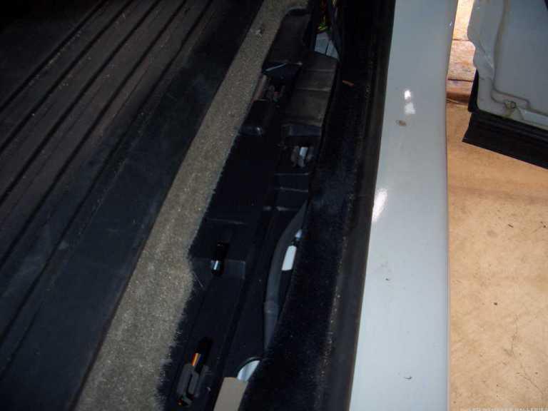
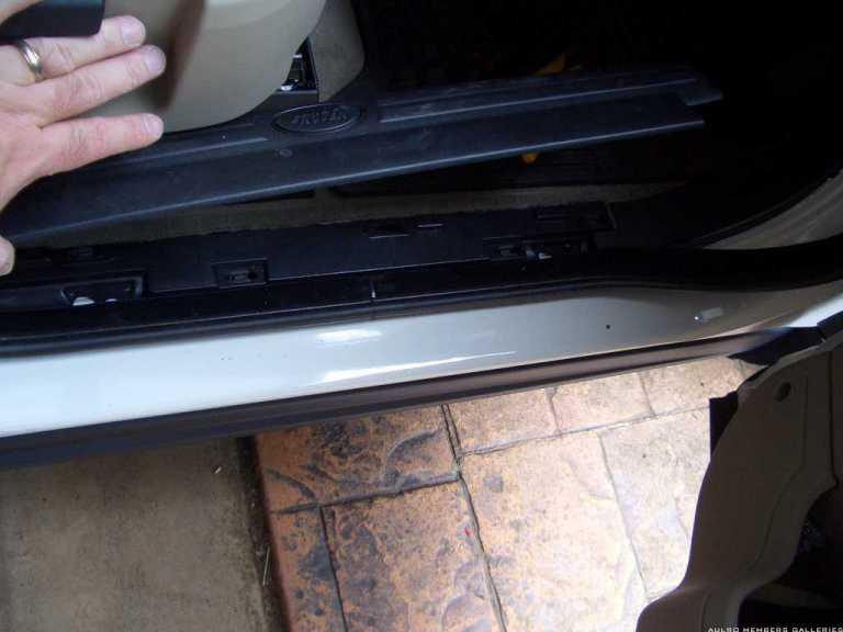
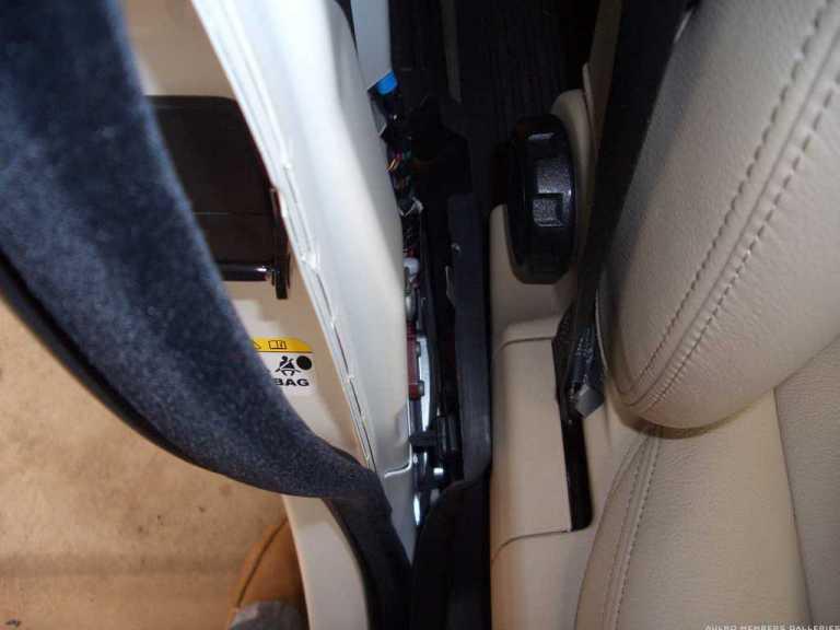
The side sill step panels are easy to remove, just be gentle lifting up. If you lose a clip that holds the sill panel down you may be searching for a while as the section they fall into is rather long & deep. You will need a long nose pliers & a magnet on a stick.
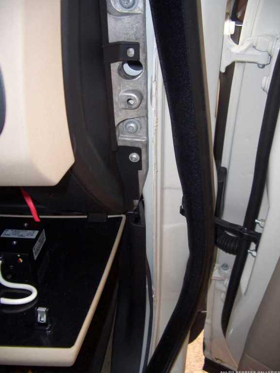
The "B" Pillar middle section just pops off with 4 platic clips, pull pull towards the centre of the vehicle to remove
You can see the cable i have run in the photo's (greyish color) It is heatshrink wrapped around the Red & Blue wires, the cable will easliy fit in between the rubber door seal & under the felt see next photo. Lift up door seal felt from being folded & place cable in between & then fold felt down again.
TBC
ChatterBox
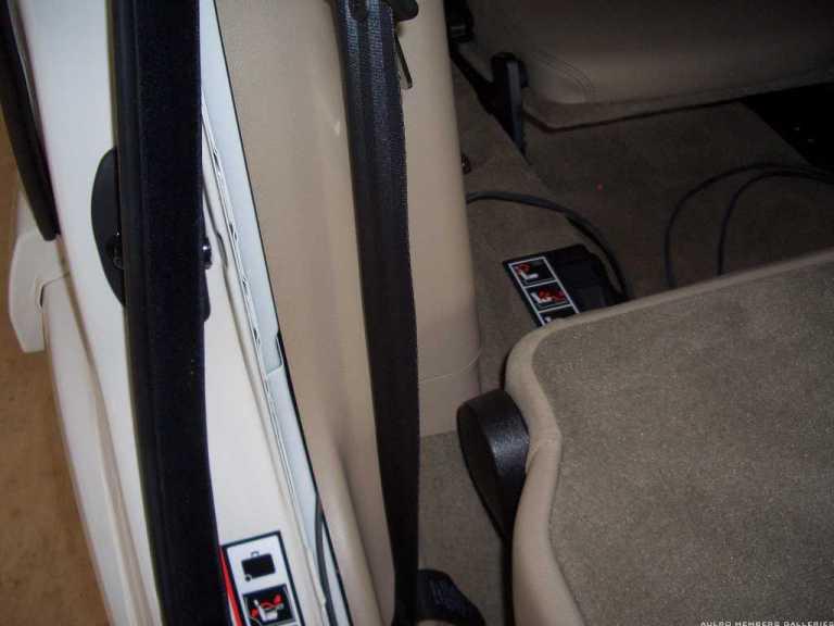
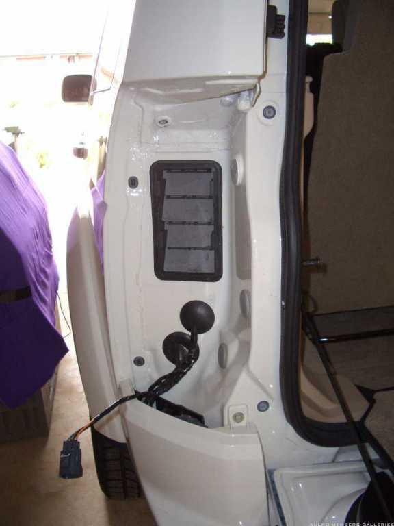
Feed the cable between the door seal & trims, push the cable along the rear 1/4 panel trim & it will drop to the bottom of the panel, stick fingers up behind panel & take out, feed to rear section & take cable out where jack door is.
Remove this panel by undoing the 3 M6 threaded bolt heads (10mm socket), when undone lift panel upwards, it will slide out. The centre clip may come off as some do, just refit it & the panel will slide back on again.
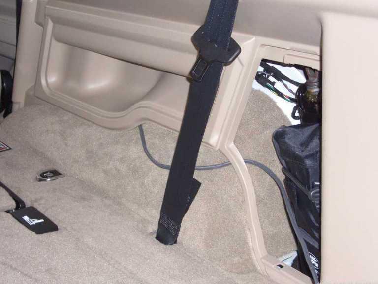
Once removed place cable from corner of jack door to under the carpet, lay cable under carpet all the way along the rear & do the same for the towbar hitch door on the passenger side.
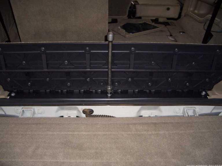
Now Remove tail light assembly as described in original post-carefully remove 2 screws
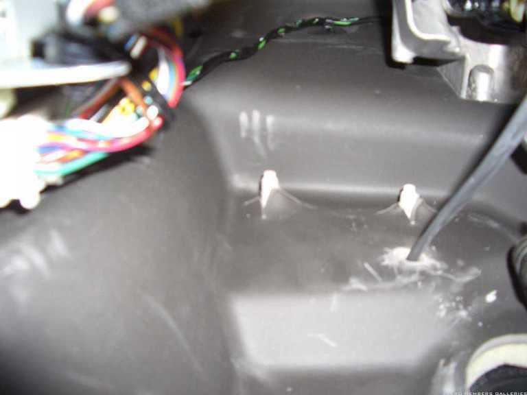
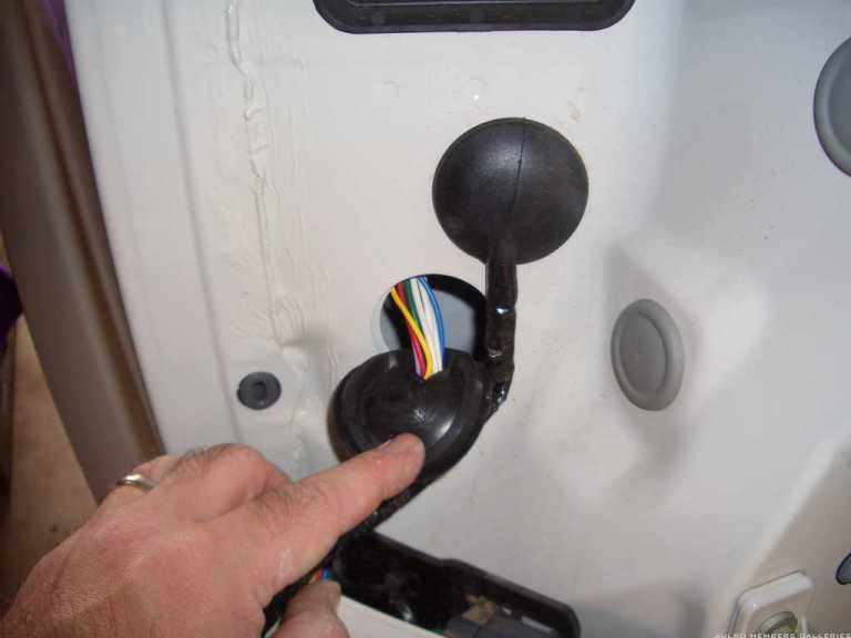
Now find these 2 rubber grommets & pirce with screw driver to feed cable from inside vehicle to outside. Dont stab ya fingers
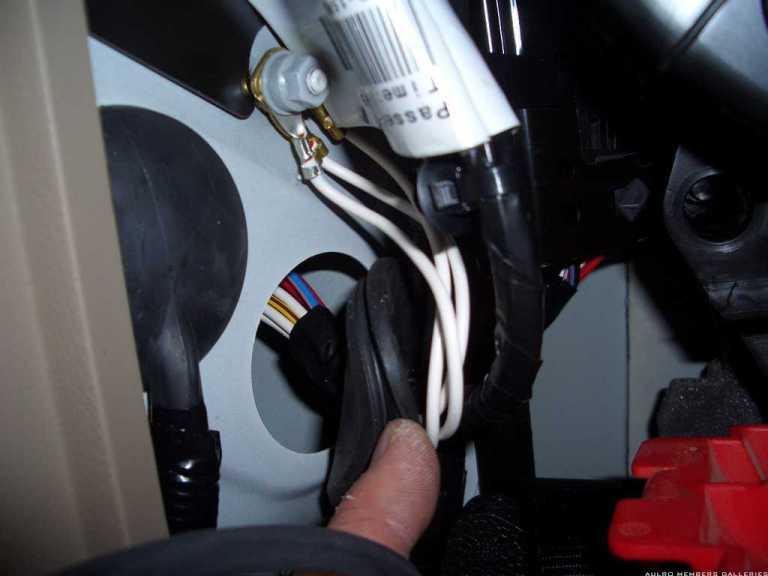
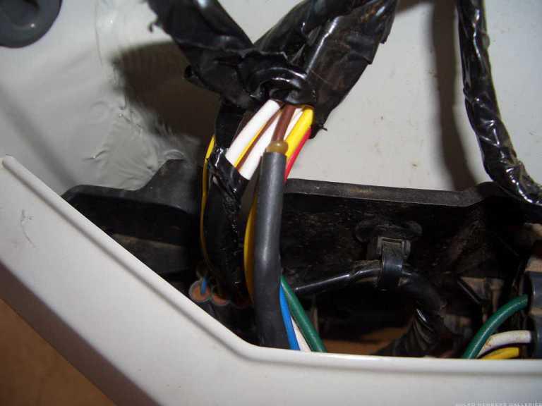
As you can see in this photo, i have located the loom i needed, It will be the one with the brown, black & red wires we need. You wil also notice the "Splice Joint" covered in heat shrink & glue. This is what we need to find after removing some of the insulation tape.
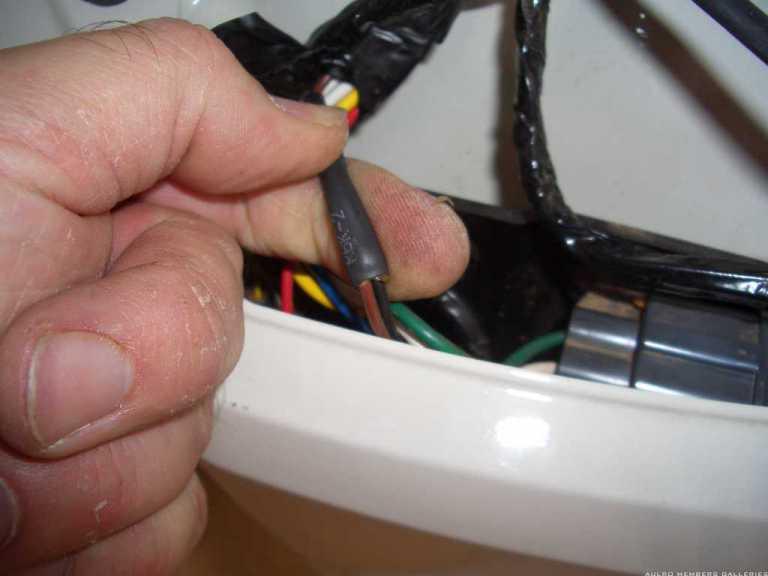
Once you have found the Splice Joint, we need to cut away the Brown wire as this goes to Pin No.5 Our trailer brake feed. Tape up the splice joint as you will have a little of the brown wire poking out & tuck away.
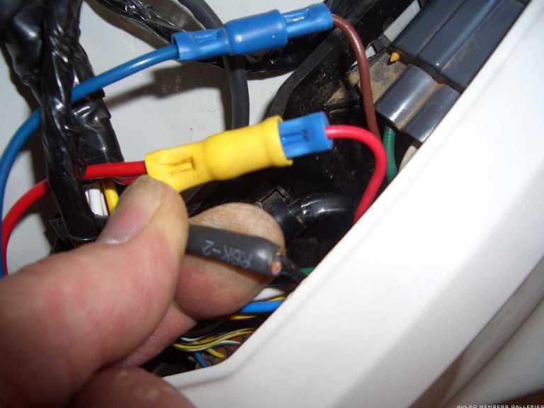
Now connect the Blue wire to the Brown wire.
Now Find the red wire in the same loom & cut in half, make sure both sections are easy to get to as you will need to crimp both ends.
Connect the Red wire from the loom & the Red wire you have run into one end of a crimp. Crimp the other Red wire to the opposite crimp & connect together.
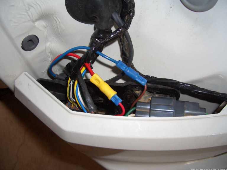
Tape up & tie out of the way, refit light & wire up the front section via a circuit breaker as per original photos.
Check opertion & away you go.
Master
Thank you Sniegy.Thank you, THANK YOU.
The info & photos you provided made this job an absolute breeze. I would have struggled for days without them & the inspiration that they provided.
I loved the minimalistic idea of the Redarc remote head so that's what I insatlled. Same postion as Sniegy's. Easy done.
I only made one change to the wiring circuit. I placed an inline 20amp fuse immediately on the end of the red wire from the EBC unit before continuing the wire run to the rear. I saw this on another circuit diagram for another brand of EBC & thought it a good insurance policy.
The only thing remaining for this installation is to test the pin5 aux brake ouput at the rear black trailer plug. That will happen today so hopefully it all works.
 Posting Permissions
| Search AULRO.com ONLY! |
Search All the Web! |
|---|
|
|
|

")


Bookmarks