

 Reply With Quote
Does this help?

 YarnMaster
does anyone here have a photo of a isuzu engine bay?
not too fussed wether its a series, county or deefer
Master
SupporterDoes this help?
84' 120" ute - 3.9 isuzu.
YarnMaster
certainly does, thankyou!
now to find one of a turbo'd one!
Wizard
Courtesy of LROCV.
Hope this helps
ForumSage
How about a rangie.
After that one above, I have some pimping to do.
Master
Hi Dougal,
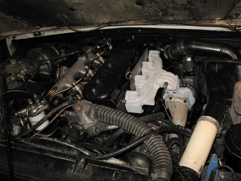
Is that intake manifold installed upside down? I have seen some Isuzu intakes with the flange on top and have been told that it doesnt give enough room to close the bonnet unless the bonnet is modified. I have seen a few 4bd1's turboed with the flange output vertical allowing a side mount where everything fits very well.
Where did your manifold come from?
Thanks.
Some pics
ForumSage
I'm guessing you mean the exhaust manifold (the one with the turbo hanging off)?Originally Posted by defenderbilby

Unfortunately they can't be just flipped due to the bolt locations, this one has had the neck cut off, flipped and rewelded.
Apparently there is a factory manifold this shape, but like the Yeti I've only seen fuzzy photos and heard rumours.
The later style manifold you show is one I have that I'll be hanging a variable vane turbo from eventually and hopefully before oil runs out a compound setup. The flange is about 20 deg off vertical and the mount flange is T3 type.

Master
Eeer yes, having a senior moment, ment the exhaust manifold.
Very impressive. Having a dual turbo system does it mean that it will spool up earlier?
Impressive welding as the manifold would have been cast. I doubt that it would give me enough room in the County with the existing alternator and a/c compressor position so I will be looking for a side mount kit. All this hopefully to happen much later though as I want this project registered by the end of the year and I have a lot to do.
Thanks for the photo.
David.
ForumSage
Yes the compound setup is intended to give me a really wide boost curve. Spool up very early and not choke. It's a work in progress so I'll be keeping people updated.
The welding on the outside of the manifold is impressive, it's survived about 16 years like that. But the inside was sh*thouse.
It was originally a split pulse manifold (web down the middle seperating pulses), that didn't line up and there was a whole raft of sharp edges and gaps.
I got to as much as I could with a die grinder and mill.
Mine has the factory size alternator (with vac pump) and AC. So plan is to make it all fit around there. That's why I originally drew it up, it was soo damn tight I had to.

Wizard
wow... too much time spent on that one Dougal 8)
where is your I/C? front mounted, full width, air to air?
 Posting Permissions
| Search AULRO.com ONLY! |
Search All the Web! |
|---|
|
|
|
Bookmarks