Page 6 of 9 FirstFirst ... 45678 ... LastLast
Results 51 to 60 of 86

Thread: Another 120 project begins

  1. #51
    Join Date
    Sep 2007
    Location
    Adelaide, SA
    Posts
    2,221
    Total Downloaded
    0
    Quote Originally Posted by Dougal View Post
    To make 200hp you'll need to pull about 18 psi intercooled to 3000rpm. That's doable on that compressor, there are just others that will do it will less drive pressure.
    My concern is whether that turbine can pass the exhaust flow.

    I am currently running a T25 with the same compressor and turbine but not VNT and not intercooled, it has the 0.49 A/R wastegated turbine housing. I'm getting 10psi at 1200rpm and 20psi a bit before 2000rpm. With the wastegate clamped shut it the exhaust turbine chokes out about 2,400rpm and kills power.
    I run a wastegate to get around that.

    The VNT turbine can deliver more boost sooner (just in case you need that) and flow more volume through the same turbine as the rpm rise. You need that because you don't have a wastegate. Instead all the gas needs to exit through the turbine. The more pressure and heat you put on a turbine the more gas you can fit through it.
    But the more pressure and heat, the more power they produce. Which produces more boost and this cycle does nothing but kill power once an engine is too big for the VNT turbo.

    To hit 200hp you need to fit about 23 lb/min of exhaust through that turbine and you need about 25kw of shaft power.
    The limit of a 0.49 A/R T25 turbine at 700C EGT and an expansion ratio to deliver that power is 19lb/min. The rest (4 lb/min) is wastegated and drive pressure is about 17psi.
    The 0.64 A/R turbine delivering the same power passes 21 lb/min and drive pressure would be ~15psi.
    To get the VNT to pass all of it you'd need the vanes to expand to an A/R ratio of about 0.9. At this point they'd pass the 23 lb/min (corrected flow is 18lb/min) with a drive pressure of ~13psi and a temp drop across the turbine of about 123C.

    So whether it'll work or not depends how far the vanes will open. If they do open far enough, then you're sorted. If they don't then you'll overboost, get high drive pressure as a result and performance will be self limiting.
    An external wastegate could be used to fix that problem. It's just an extra complication.
    Yeah, I was working through the 4BD1T Turbo Sizing and Performance Prediction thread in my spare time & mapped out various power outputs for the T25 60 trim compressor map at 1000, 2000 and 3000 RPM, assuming "effective intercooling" and an A/F ratio of 18:1.


    Compressor efficiency looks reasonable at around 70% between 2000 and 3000 RPM.

    I wasn't certain how VNT turbine sizing works, but have guessed the 0.64 A/R marked on the casting to be scroll geometry A/R without the VNT vanes (or perhaps with vanes fully open). The closest dimensioned turbine I can find is the Garrett "Disco Potato" 53.9mm 76 trim turbine with a 0.64 A/R housing which seems to choke out at a corrected flow of 18 lbs/min. - Not sure what the flow is corrected to, but seems considerably lower than the mass flow at the compressor, and what goes in must come out, right?
    That's why I thought I may need an external wastegate to make the 150kW / 200hp, however I still don't have an understanding of drive pressure / back pressure / shaft power, and how they relate to the turbine map & choke flow.
    Keeping a keen eye on the turbo sizing and performance prediction thread.

  2. #52
    Join Date
    Sep 2007
    Location
    Kiwiland
    Posts
    7,246
    Total Downloaded
    0
    Quote Originally Posted by Offender90 View Post
    Yeah, I was working through the 4BD1T Turbo Sizing and Performance Prediction thread in my spare time & mapped out various power outputs for the T25 60 trim compressor map at 1000, 2000 and 3000 RPM, assuming "effective intercooling" and an A/F ratio of 18:1.
    What are you using for VE? You are showing higher boost for the same power as my calcs.
    Just picking on the 3000rpm 130kw point, I'm only showing 13psi with 70% comp efficiency and 60% intercooler effectiveness.

    Compressor efficiency looks reasonable at around 70% between 2000 and 3000 RPM.

    Quote Originally Posted by Offender90 View Post
    I wasn't certain how VNT turbine sizing works, but have guessed the 0.64 A/R marked on the casting to be scroll geometry A/R without the VNT vanes (or perhaps with vanes fully open). The closest dimensioned turbine I can find is the Garrett "Disco Potato" 53.9mm 76 trim turbine with a 0.64 A/R housing which seems to choke out at a corrected flow of 18 lbs/min. - Not sure what the flow is corrected to, but seems considerably lower than the mass flow at the compressor, and what goes in must come out, right?
    That's why I thought I may need an external wastegate to make the 150kW / 200hp, however I still don't have an understanding of drive pressure / back pressure / shaft power, and how they relate to the turbine map & choke flow.
    Keeping a keen eye on the turbo sizing and performance prediction thread.
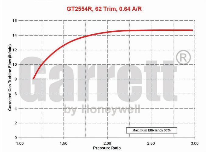
    The disco potato is a significantly bigger turbine. This one:

    Has turbine measurements which match mine. My best guesstimates put my 0.49 housing as scaling the line down to about 13.3 lb/min corrected choke flow.

    But yes the vane behaviour and equivalent A/R is the big ? Can it adjust either side of the housing A/R ratio equally or only much smaller and not much bigger? The turbine efficiency of the VNT's is also a lot lower (drag from all those vanes at a less than ideal angle).

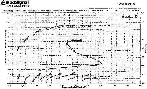
    This one is incredibly fuzzy, but it shows the limits of operation for an unknown VNT model:


    There is an FSAE data dump on the web with GT1541V (#700960, application includes vw 1.2tdi allegedly) maps including turbine, the A/R is 0.42 if you want to compare against fixed geometry housings.
    Turbine maps are corrected to STP. It's a mental battle doing the calcs for real flow to corrected as you have to juggle pressure at the inlet, expansion ratio and power or real flow to keep corrected flow on the target.

    *edit*
    I've just compared the GT1541V turbine map (0.42 A/R) against a GT1544 which appears to use the same 58 trim turbine with a 0.34 A/R housing.
    It looks like the VNT maxes out at the stated A/R. VNT with 0.42 only hits ~7.5 lb/min corrected. Fixed with 0.35 A/R is ~6.3 lb/min corrected.

    This does not bode well for your VNT25. It may choke and spike both boost and drive pressure to kill your top end performance.
    Last edited by Dougal; 17th September 2013 at 05:51 PM. Reason: VNT vs fixed geometry.

  3. #53
    Join Date
    Sep 2007
    Location
    Adelaide, SA
    Posts
    2,221
    Total Downloaded
    0
    Using 0.9 VE at 1000 & 2000 RPM, and 0.8 @ 3000 RPM.

    I suspect the difference may come from either my Density to Pressure ratio guestimate or the Air to Fuel ratio assumed. I assumed A:F 18:1 and a sliding scale for Density to Pressure ratio conversion from PR=1.25*DR @ DR<1.4 to PR=1.1*DR @ DR>2.0 without actually working out intercooling effects.
    I used a spreadsheet to generate all the values & can email if you're interested.

    When you say the disco potato turbine is significantly larger, I was under the impression both disco potato turbos used a T25 sized turbine with a larger compressor housing. I was using the data off the smaller one with a 53.9mm wheel, 76 trim in a 0.64 A/R housing.

    Garrett's VNT-25 turbine on the other hand uses a 52.7mm wheel, 77 trim in a "0.64 A/R variable vane" housing. Wouldn't the two turbines be fairly similar in size, or am I missing something obvious?

    This is the chart I was referring to:


    When it comes to turbine charts in general, and VNT turbines in particular, I must admit it is all somewhat French to me - still a lot of reading I have to do.

  4. #54
    Join Date
    Sep 2007
    Location
    Kiwiland
    Posts
    7,246
    Total Downloaded
    0
    Quote Originally Posted by Offender90 View Post
    When you say the disco potato turbine is significantly larger, I was under the impression both disco potato turbos used a T25 sized turbine with a larger compressor housing. I was using the data off the smaller one with a 53.9mm wheel, 76 trim in a 0.64 A/R housing.

    Garrett's VNT-25 turbine on the other hand uses a 52.7mm wheel, 77 trim in a "0.64 A/R variable vane" housing. Wouldn't the two turbines be fairly similar in size, or am I missing something obvious?
    Gotcha now. I didn't realise the VNT25 had a much larger trim than the wastegated versions. The VNT turbos of now appear to be using the same turbine as the wastegated versions.

    So yeah 17lb/min corrected choke flow would be the best number we've currently got. But turbine efficiency could be as low as 45%.
    My earlier example of the VNT with an equivalent to about 0.9 A/R came out with corrected choke flow of 17.9 lb/min.
    So now it's within the margin of error. Definitely close enough to try.

    *edit*
    Just a general disclaimer. I am still bug checking all these turbine calcs.
    Last edited by Dougal; 18th September 2013 at 06:34 AM. Reason: disclaimer.

  5. #55
    Join Date
    Jan 1970
    Location
    'The Creek' Captain Creek, QLD
    Posts
    3,724
    Total Downloaded
    0
    Quote Originally Posted by Offender90 View Post
    ...

    I suspect the difference may come from either my Density to Pressure ratio guestimate or the Air to Fuel ratio assumed. I assumed A:F 18:1 and a sliding scale for Density to Pressure ratio conversion from PR=1.25*DR @ DR<1.4 to PR=1.1*DR @ DR>2.0 without actually working out intercooling effects.
    ...
    I've been too busy to update the stuff I have been adding to the turbo sizing thread. I only intended the rough conversion for PR to be used for the first pass guesstimate of adiabatic efficiency. The proposed next post that I haven't had time to finish addresses PR to DR.

    PR = DR x T2/T1
    where
    PR is pressure ratio (P2/P1)
    P2 & P1 are absolute pressures at outlet & inlet, P1 = ambient - losses
    DR is density ratio (D2/D1)
    T2 is absolute Temp in K at outlet (after intercooler if fitted)
    T1 is ambient temp in K

    A problem with that is T2 increases with pressure (and reduces with increased efficiency), so making it difficult to calculate PR directly. I find it easier to calculate DR for a range of PR, to create a 'look-up table' to find the PR.

    Then I will address some of the other stuff.

  6. #56
    Join Date
    Sep 2007
    Location
    Kiwiland
    Posts
    7,246
    Total Downloaded
    0
    Quote Originally Posted by Dougal View Post
    To hit 200hp you need to fit about 23 lb/min of exhaust through that turbine and you need about 25kw of shaft power.
    The limit of a 0.49 A/R T25 turbine at 700C EGT and an expansion ratio to deliver that power is 23lb/min. The wastegate is basically shut and drive pressure is about 25psi.
    The 0.64 A/R turbine according to the maps can't quite deliver. It can only produce 22kw from that pressure and flow with 20psi drive pressure.
    The lower efficiency of the VNT (I'm using 0.55 vs 0.65 for the T25 turbines) means it needs cranked closed to a corrected flow of about 11 lb/min. This will spike the drive pressure to ~33psi.

    However. I'm finding my actual results are giving better turbine performance than the predictions. Which to me suggests that exhaust pulse energy is driving the turbine harder than the published charts which are for steady flow.
    I was certainly getting more than 17psi boost from the T25 0.64 A/R turbine with the wastegate clamped at 3000rpm. 2500-3000rpm was the operating point where the T2560 turbo that I built with the 0.64 housing was truely impressive.
    I found a bug in my spreadsheets (formula referencing wrong column) and have corrected the post quoted above.
    The 0.49 T25 shows wastegate almost clamped to provide that 25kw.
    The 0.64 T25 is showing as not making 25kw.
    The VNT would need to be cranked down below full open vanes.

    But my measured results (boost, drive, egt etc) are showing better than predicted. I'm putting this down to exhaust pulse energy where the turbine maps are developed using steady flow.
    It looks like you can account for this in a rough way by bumping turbine efficiency up. But I'm hoping to find something better.
    But I'm also unsure whether the temperature used for correction is 0C, 15C or something else. Borg Warner use 15C (59F), 0C is pretty common in chemistry and I can't remember what Garrett use for their compressor maps.

  7. #57
    Join Date
    Jan 1970
    Location
    'The Creek' Captain Creek, QLD
    Posts
    3,724
    Total Downloaded
    0
    Quote Originally Posted by Dougal View Post
    I found a bug in my spreadsheets (formula referencing wrong column) and have corrected the post quoted above.
    The 0.49 T25 shows wastegate almost clamped to provide that 25kw.
    The 0.64 T25 is showing as not making 25kw.
    The VNT would need to be cranked down below full open vanes.

    But my measured results (boost, drive, egt etc) are showing better than predicted. I'm putting this down to exhaust pulse energy where the turbine maps are developed using steady flow.
    It looks like you can account for this in a rough way by bumping turbine efficiency up. But I'm hoping to find something better.
    But I'm also unsure whether the temperature used for correction is 0C, 15C or something else. Borg Warner use 15C (59F), 0C is pretty common in chemistry and I can't remember what Garrett use for their compressor maps.
    AFAIK Garrett use 545 R and 28.4" Hg for their compressor maps, and Borg Warner use 873 K for turbine, 293 K and 981 mbar for compressor.

  8. #58
    Join Date
    Sep 2007
    Location
    Kiwiland
    Posts
    7,246
    Total Downloaded
    0
    Quote Originally Posted by Bush65 View Post
    AFAIK Garrett use 545 R and 28.4" Hg for their compressor maps, and Borg Warner use 873 K for turbine, 293 K and 981 mbar for compressor.
    So back in useful units.
    Garrett 30C/303K and 96.3kPa for compressor. I had 298K/25C written down for garrett with the same presssure but I didn't write down the source.

    Borg Warner are using 59F (15C/288K) in the matchbot for turbine correction. Where did you find 873K?
    I'm very happy with the correlation I'm getting on turbine results with borg warner using 288k and 101.3kPa for turbine correction. But the compressor power doesn't make sense, I've got some figures I've you'd be kind enough to check them in the prediction thread.

  9. #59
    Join Date
    Sep 2007
    Location
    Kiwiland
    Posts
    7,246
    Total Downloaded
    0
    Another bug found.

    145kw at 3000rpm data points.

    17psi boost = 18.3kw shaft power.
    ~21psi drive pressure on a 0.49 T25. Wastegating 5 lb/min
    ~19.5psi drive pressure on a 0.64 T25. Wastegating 3.5 lb/min
    ~20psi drive pressure on a VNT25 with corrected flow of ~17 lb/min it's trying to produce ~20kw of shaft power. So you'll be into the boost spiral but not much. It should cool your EGT enough with only a few more psi boost to reach equilibrium.

    Now I've got work to do.

  10. #60
    Join Date
    Jan 1970
    Location
    'The Creek' Captain Creek, QLD
    Posts
    3,724
    Total Downloaded
    0
    Quote Originally Posted by Dougal View Post
    So back in useful units.
    Garrett 30C/303K and 96.3kPa for compressor. I had 298K/25C written down for garrett with the same presssure but I didn't write down the source.

    Borg Warner are using 59F (15C/288K) in the matchbot for turbine correction. Where did you find 873K?
    I'm very happy with the correlation I'm getting on turbine results with borg warner using 288k and 101.3kPa for turbine correction. But the compressor power doesn't make sense, I've got some figures I've you'd be kind enough to check them in the prediction thread.
    I took the temp and pressure for Borg Warner compressors from the example map

    from this page from Borg Warner and it is the same as every Borg Warner 'K' series compressor map I have ever seen clearly states same reference values, i.e. 293 K and 981 mbar.

    From another page of the same Borg Warner website I took the reference temperature from this example turbine map


    I've had a look and seen where you got the turbine reference temp (59 F) from Matchbot. It strikes me that 59 F (15 C) is a strange temperature to correct exhaust gas temperature to, but we have to work with what we have!

    Matchbot only works with 'EFR' and 'S' series turbos, which causes me to wonder if the difference is whether the Borg Warner turbo is from Europe 'K' series, or from USA 'EFR' and 'S' series?

Page 6 of 9 FirstFirst ... 45678 ... LastLast

Bookmarks

Bookmarks

Posting Permissions

  • You may not post new threads
  • You may not post replies
  • You may not post attachments
  • You may not edit your posts
  •  
Search AULRO.com ONLY!
Search All the Web!