

 Reply With Quote
Good hustle everyone! I'll keep an eye on it in my upcoming adventures, and raise it the next time it visits the workshop.

 Wizard
Subscriber
Wizard
SubscriberYes, It was Daniel from Mungo who suggested I get it looked at when it got serviced. never happened again.Originally Posted by Toxic_Avenger

[SIGPIC]
2012 LR Defender 90 (BERT) Gone
2012 Husqvarna WR 300
2014 FPV F6 Gone
2005 D3 SE V8
2011 D4 V8
2016 Moto Guzzi California Audace.
TopicToaster
SubscriberGood hustle everyone! I'll keep an eye on it in my upcoming adventures, and raise it the next time it visits the workshop.
-Mitch
'El Burro' 2012 Defender 90.
TopicToaster
SubscriberTook a nice drive thru Nundle state forest today.
Sadly, I did not get any pics, however it was a very picturesque area to explore (see the map below).
[ame]http://www.forestrycorporation.com.au/__data/assets/pdf_file/0003/510807/fossicking-area-map-nundle-state-forest.pdf[/ame]
Tracks range from graded dirt logging roads, to some pretty gnarly tracks of rock, clay and mud holes.
Most of it is pine plantation, however there are areas of eucalypt forest, and areas that have been recently logged. It's all at altitude too, it was snowing up there in early July, as the pic below shows:
All in all, today's afternoon trip was about 5 hours travel, with 3 of those being exploring off tarmac. It's a massive area, and even just taking a random track wherever I saw it, I still only managed to drive around the Chapmans farm / Hoads Farm area on the map, and circled around baldy knob (where the firetower is). Being pine forest, some areas are stripped bare, some are old and overgrown (one sign showed an area was planed in the early 70's),but all make for good driving.
I'll get some pics next time. It really is a nice area, and I'd recommend anyone who is in the area stop by for an explore.
-Mitch
'El Burro' 2012 Defender 90.
TopicToaster
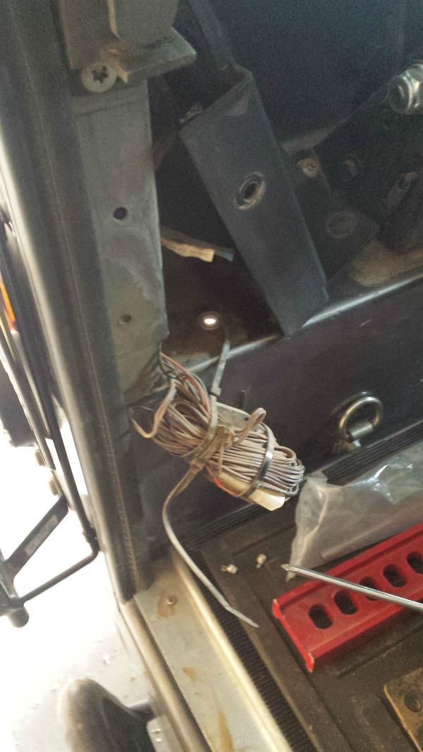
SubscriberForgive me, I have sinned.
My wiring job went AWOL somewhere along the line after a few hasty re-installations of some accessories I had not fully moved into the ex box.
After re-connecting the air compressor and doing a few mud runs on the 'dirty weekend' above,
This...
somehow turned into this...
It's all good though, I removed the batteries, got out the hose and flushed all the mud and crud out. The RBS and ACR units loved it, being water proof and all that
I previously mentioned the dead space behind the battery (on the batt box wall closest the door), and to 'watch this space' for future surprises.
The cat's out of the bag now, and the plan is to use this space behind the batteries (closest to the door, pic upside down for some reason)...
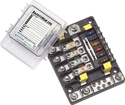
To house one of these skookum choochers
The specs:
Blue sea systems Safety Hub 150, 10 circuit fuse block.
Uses AMI fuses for loads up to 200A (think inverters, stereo amplifiers, other fuse blocks etc), and ATC fuses (standard automotive style) for other loads up to 30A (lights, accessories etc). Total fuse block can handle up to 280A, so a solid little device in a really attractive form factor / footprint.
If I were starting my ex box from scratch, I'd be working one (or two) of these into the design for sure!
In other news, I've been trying to work out cable routing for lights / fridge / other connections in the rear loadspace of the vehicle. I've got a rijidij rear bar on order, so there will be some interesting things happening there, necessitating the need for power back there. The factory wiring for the tail lights and trailer wiring runs along the LHS chassis, and this is one way I can do it, otherwise I can try to run wiring thru the window trim inside the vehicle. Much of a muchness either way, but still something to contemplate.
In keeping with the theme of off-licence parts in this build (this landy is looking to be more boat parts and knight-rider than defender), I spied some PVC corrugated conduit at bunnings which will make a suitable semi-watertight cable routing solution for fore/aft power out of the battery box. This will work as a suitable link between the ex box, and the inside of the battery box for all the small little wires that need to go between (signal wires for the ACR / RBS, air compressor switch wiring, etc). It's normally used for household / commercial power installation. I've seen some very nice (but horrendously expensive - like $15 per meter, min lot of 10m) conduit from Tyco / Flexicon which is temp reisitant to 150 celsius, but this stuff is good for 60 degrees, and was 13 bucks for 10 meters. Winning
As per this thread I started, I was trying to work out a way to get power neatly from the battery box to inside the vehicle up on the wheel well, but will probably just use an existing hole in the battery box lid near the seat rail, to get the air compressor wiring into the box, and just grommet it.
Wiring to front and back can be done with tubing and along the chassis rail, leaving the battery box via a cable gland or something... I'll probably just wing it when the time comes.
Anderson plug for aux battery and rear of vehicle is still on the cards, as is some camp lights on the roof rack and in the load space, as well as some kind of switch board in the back for control of the lot. Once all this crap is sorted, it will be easy to chop and change accessories as needed with minimal fuss.
-Mitch
'El Burro' 2012 Defender 90.
TopicToaster
SubscriberJust thought I'd post a quick instructable for an off-licence use of some bunnings electrical conduit accessories for managing cables in a dual battery install.
The 70mm2 cable I use is fairly flexible, but still needs some coaxing around 90 degree bends.
Looking thru the bunnings aisles, I spied the Deta range of conduit bends, which got me thinking...
The factory earth cable uses a 90 degree plastic bend to train the cable to the earth post. I could recreate this using these parts, simple tools and electrical tape or heat shrink...
Step 1 - Acquire hardware
Deta 20mm conduit bends 3 off @ $1.05 ea
Step 2 - Dremel action
Using a dremel and small cutoff wheel, cut a slit along the side of the bend (not the large or small radius). I cut only what was necessary, and took approx 10mm
Step 3 - Tidy up
I used a deburring tool to slice off the dags as needed. But moved to a dremel and sanding drum as it was a little faster.
Step 4 - Insert cable
Pretty self explanatory.
But pro tip- use the off cuts of the PVC to find the melting point and properties of the plastic. My particular sample seems to be a 'thermosetting' plastic, meaning a waft of heat and it becomes very pliable. This would allow installation along a cable where you don't have access to an end. Be sure to tape it closed while it's still warm to allow it to 'set' on the cable before the next step
Step 5 - Tape or heatshrink
Personal preference. I'll do this once I fit it on the car.
I hope you enjoy laying your cable as much as I did!
-Mitch
'El Burro' 2012 Defender 90.
Loud Mouthed Rat Bag
Nothing wrong with that Battery Box at all. Looks just like a Pro Hart.
Cheers, Billy.
Keeping it simple is complicated.
TopicToaster
SubscriberOr pro heart surgery gone wrong...
This came in the mail last week.
Loaded it up with some MIDI fuses I picked up in newcastle over the weekend. I've discovered whitworths marine in Broadmeadow, which has some cool stuff to get me into trouble if I ever need it
Spent most of the afternoon driving Newcastle>Tamworth, so just managed to do a quick mockup this afternoon in the fading sunlight, and the fitment should be primo. MIDI fuse lugs point towards the rear of the vehicle, the earth points face towards the bottom of the battery box, and the positive feed is in a spot with plenty of space to be insulated from wayward shorts. So looking into the battery box from the drivers seat will have it installed in the same orientation.
While in Newcastle, I also stopped by ARB to have a squiz at some battery state of charge monitors. There are some very interesting devices out there that can calculate the remaining battery capacity and instantaneous amp draw thru either a shunt on the negative cable, or a hall effect sensor. It would be a nice to know gauge for the vehicle, but might just be another 'gadget' to complicate the electronics further. The simple method would be to get a couple of cheap volt meters off ebay and hook one to each battery, and use the 0% SoC voltage to work out what power you have left.
I planned to leave empty handed from ARB, but this struck me as a nice accessory for the roof rack - it's a hi lift / shovel holder bracket, and should allow me to re-assemble the hi-lift and keep it up there as opposed to resting in peices between the driver's seat box and the post clanging around the back loadspace. I don't own a shovel, so that might have to change in the coming days... so I can get some imstalled pics happening.
Driving today, saw a few nice deefers, but I was flying incognito in the work car, so my waves were unnoticed. One black puma in the Kotara homemakers carpark near dan murphys, and another white one in aberdeen with 110 DFR plates. Looked tuff!
-Mitch
'El Burro' 2012 Defender 90.
TopicToaster
SubscriberProductive day today, spent most of the day working out the kinks in the battery box.
Worklist was:
- Tidy up the stereo wiring for the sub/amp and associated power cabling for the amp and air-compressor.
- Re-route the ex box power feed and main body earth cables
- Install a cable feed for wiring between the ex box and the battery box.
Stereo wiring
The vehicle came into my posessions with an aftermarket stero. It's got soundstream speakers, an alpine sub/amp and head unit. The wiring for this however left a bit to be desired, with tufts of cables scrunched up, zip-tied and stuffed where the installers thought no one would ever find them. That is, until I came along
Here is one of many examples- speaker cabling behind the rear speaker.
There's probably 10+ meters of copper there doing absolutely nothing but add resistance to the circuit, and getting less power to the speaker to actually do it's job. That job is on the cards, but will be tackled another day. Even for an installer, ther'd be 1 snip of the side cutters, a couple of solder sleeves, and they'd get another installs worth of cabling to use for the next job! But I digress...
The order of the day was the sub/amp wiring. The amp has a pair of RCA cables and a remote wire that comes from the head unit, and the sub itself is powered from a + and - from the battery.
I armed mysself with some 16mm split conduit, and a selection of electrical tape, harness bits (T's, Y's, and ends- these things are awesome), and got to work.
I'll spare you mob the details, but this is the outcome:
Here we see it all wrapped up. Excuse the gal brackets holding the amp onto the box- not my work!
You can see the end connectors and a Tee piece which really do neaten up the install. Easily sourced from supercheap, they make this kind of thing an easy task. The black remote wire, and the grey RCA cables at the amp, run thru the loom on the left, under the mat on the trans tunnel, and up under the dash to the head unit. The Red power cables are the positive and negative power for the amp, and run down thru the Tee piece...
...and thru some P clamps along the trim panel near the load space. This should clear the seat sliding mechanism, but might be a problem if I ever go for that mulgo rail. I'm short, so shouldn't ever have that problem!
A number of months back I sourced some rubber grommets with the 'tails' on them for mounting things into and out of the battery box or ex-box. Today I got to use one, as I'd previously changed my mind on their intended application and put them away in a parts box.
Here we see the location of the standard hole which is put into the seat box, and sealed with a rubber grommet. What I've done here is drilled it out to approx 30mm for use with my grommet. You can see the rivet which is used to hold the brace for the seat mounts in place- I needed to ensure I wasn't too close to that brace when enlargening that hole.
After crackling the lube out (silicone spray- my favourite libation), I managed to squeeze a heap of cables thru, like thus:
The wires to the right go to the air compressor which I've mounted on the rear wheel arch. The wires for this (control wires, and power) have been given the same split conduit and tape treatment, and should be relatively protected from the elements.
On the inside of the box, the amp/sub and air compressor are hooked into the safety hub 150 (upside-down pic is upside down).
Almost pornographic.
I fused the air compressor wiring at a slightly higher 50A than the factory 40A maxi fuse for one wire, and 40A on the other. 40A fuses are what were supplied with the loom, but there were some online reports of these fuses blowing with longer cable runs, and higher than normal ambient air temps and compressor duty cycles. I'll suck it and see what happens here, and report back if anything blows / melts / kills us all.
I still need to hook up the primary Positive and negative wires from the AUX battery to this fuse hub, but after that, It'll be an easy job to hook in other little accessories as needed. The negative bus is along the bottom, and the standard ATC fuses are near the white fuse puller for circuits <40A. The blank 100A fuse position will be for a wire run that goes into the rear load space, Which will exit the rear of the battery box, go along the chassis loom, and enter the load space near the bundle of madness which I pictured above. This will feed things like load space lighting, exterior lighting, and if I want to get real crazy, rock lights in the wheel wells for night driving.
I swear I'm not afraid of the dark
-Mitch
'El Burro' 2012 Defender 90.
TopicToaster
SubscriberPart 2!
Job 2: Re-route the ex box power feed and main body earth
I'ts no secret that the wiring job I worked hard for went to **** when I started adding accessories direct to the battery. Just the sheer complexity of all the crap I've got going on in here makes it difficult to see, let alone know what's happening.
The setup connections are:
Cranking battery Positive
- Main positive to 500A fuse block / starter and factory fuse block / vehicle electrics
- Cable to the ACR for charge controlling
Cranking battery Negative
- Main body earth (This meets up with the ex-box negative feed links back at the chassis earth)
- Cranking battery / AUX battery negative link
- Safety Hub 150 Negative cable
- Winch Negative cable
AUX battery Positive
- ACR cable
- Winch positve (to RBS, then to the T-type Fuse block)
- Ex-Box pisitive feed (now thru a new cable gland)
- Safety Hub 150 positive feed
- Terminal MBRF fuse holder and Ex Box positive feed cable, which also had driving lights and other crap connected to it, making a mess
AUX battery Negative
- Main/Aux battery negative link
On the above list, the Green items are the ones I've worked on today, and have added or relocated from previous posts. The red items are the ones I've deleted, or moved back to the safety Hub
Long story short, you can see why I went the Blue top optimas with the extra post terminals over the yellow tops without!
Part of the plan today was to relocate cables on the inside wall of the battery box (trans tunnes side). Here there were a few cables coming in the centre area, getting in the way, and cluttering the area where I'd like to store some other small items like the jack (if it fits), or small parts.
I've just used cable glands to get the cables in and out. They are IP rated, and support the cable from any risk of chafing and shorting out. Cheap too, at a couple of bucks a piece from your favourite electrical wholesaler.
Here is the ex box positive feed, which now enters from the rear of the battery box, alongside the winch Negative cable. Pro points for duct tape covering a draining hole in the bottom of the battery box! I removed the tray and it had filled with mud from a the dirty weekend- even after I'd hosed it all out! One day, I might install a drain valve or something, and then seal it all up with silicone.
Here, I've added a cable gland for the Main chassis negative cable, which is tucked behind the starter motor positive cable. The winch positive enters alongside it.
Further along, I've blanked off the factory hole with a ~30mm (inch and a quarter, IIRC) blanking grommet. The other hole will be treated the same, once I remove the wiring there, and move it to the white cable gland which I've just recently installed (in the middle of the above pic)
This brings me to my new innovation, which I call the ****- Toxic's Wide Apeture cable Tunnel
I've drilled a hole in the bottom of the ex box, and installed a flexible corrugated cable gland. A similar hole / galnd has been drilled into the inboard side of the battery box, and pictured above.
Between the two, there is a short (<20cm) length of conduit...
...Allowing the **** to do it's thing- allowing easy access between the battery box, and the ex box! I've inserted a red wire into my **** for dramatic effect here
This will be perfect for small cables for switches which will be mounted on the ex box, and might need to exit the battery box to go to accessories in the rear as I described in the previous post. The first items to go thru my **** will be the ACR/RBS switch control wires, and Air compressor switch wires.
My job tomorrow will be to finalize most of this, get some of the switch wiring tidied up (again! I've got some loose connections going on) and get the battery tray back in, and take it for a drive (if there's time!).
Booze Revooz for tonight was a glenlevit 15yo scotch and soda. notbad.jpeg.
Stay tuned!
-Mitch
'El Burro' 2012 Defender 90.
Loud Mouthed Rat Bag
Question for you Mitch. Is that coil of wire in the speaker circuit, as supplied by the factory? Perhaps a shortened 110 loom? In any event you should get rid of it. At the risk of stating the bleeding obvious. Not only does the extended length increase Voltage drop it all acts as a Coil, i.e. it will induce unwanted currents into the circuit and muddy the sound from the speakers.
Cheers,Billy.
Cheers, Billy.
 Posting Permissions
| Search AULRO.com ONLY! |
Search All the Web! |
|---|
|
|
|


")

Bookmarks