Page 1 of 7 123 ... LastLast
Results 1 to 10 of 66

Thread: DIY Map/Maf enhancer / manipulator

  1. #1
    Join Date
    Jan 1970
    Location
    Melbourne - Eastern sector
    Posts
    963
    Total Downloaded
    0

    DIY Map/Maf enhancer / manipulator

    I am about to go down the more boost, VNT and big fuel map route for my TD5 ute

    I have been looking at the options available to us from Alive, BAS, IRD in relation to boost boxes / dual channel controllers etc.

    Then I stumbled across "MAF/MAP Enhancer"


    Has anyone tried doing this to the MAF or MAP sensors on a TD5 engine???

    well i got bored the other night and setup this up.


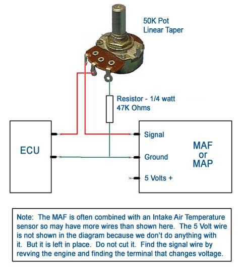
    I had the MAF connected to a 5v source and manipulated the signal back to the ECU with a 50K liner POT and 47k 1/2 watt resistor (see pic above). With the PC fan blowing on the MAF i could get up to 3V on the signal side of the MAF. Which i thought was a lot given the amount of air i was flowing at the time. Even blowing on it would hit about 2v. Go figure!! So by turning the POT i could easily bring the volts back to 0 with the PC fan going!! Successes!

    Question to anyone who understands more about this stuff then i do...what would be the best way to work out the right maximum resistance to use on a MAF or MAP on the TD5 engine?

    Do you think this is all that is in the adjustable tuning boxes are made of??
    Parts cost me about $14

    Mick

  2. #2
    Join Date
    Feb 2011
    Location
    Brunswick, Victoria
    Posts
    3,778
    Total Downloaded
    0
    Don't know what is in the tuning boxes, but hopefully the tuners are doing a bit more than that.

    The "problem" with the sensors is the output is run into an analog to digital convertor, and to maintain resolution the maximum value is set to something less than 5V. When you hook up a VNT or a big tune the airflow measure by the MAF exceeds the maximum value coded in to the ECU, and the ECU sees this as a fault.

    If you hook up a pot as shown you are simply attenuating the signal across the board. While it will reduce the output of the MAF/MAP so it avoids a fault condition, it also introduces an error that effects all readings from the sensors.

    A better solution might be to look for a voltage limiter that clamps the maximum output to a value that avoids faults.

    I think justfishing may have done something like this after finding a boost box he purchased was non functional.

    cheers
    Paul

  3. #3
    justfishing Guest
    Hello,
    I have been down the track you are going in many times. I did make a volt switch and post it here explaining how to make it, any problems PM me. There are many very good tuners on this forum. Fooling sensors is great but not to trip the ECU at maximum possible volts without limp mode is the way to go not to limit across the whole range as Offtrack already said. The best way to make the MAF not go to limp mode is to make the diameter of it bigger you do not even have to have do any electronic tricks. At low RPM you want all the volts you can get form the MAF not to reduce it, you want that VNT to SPIN.
    Ian

  4. #4
    Join Date
    Jan 1970
    Location
    Melbourne - Eastern sector
    Posts
    963
    Total Downloaded
    0
    Quote Originally Posted by justfishing View Post
    Hello,
    I have been down the track you are going in many times. I did make a volt switch and post it here explaining how to make it, any problems PM me. There are many very good tuners on this forum. Fooling sensors is great but not to trip the ECU at maximum possible volts without limp mode is the way to go not to limit across the whole range as Offtrack already said. The best way to make the MAF not go to limp mode is to make the diameter of it bigger you do not even have to have do any electronic tricks. At low RPM you want all the volts you can get form the MAF not to reduce it, you want that VNT to SPIN.
    Ian
    Thanks for the info

    I came across these guys

    Split Second

    they make VC2-5

    Adjustable Voltage Clamp for 5V operation
    and
    Modifier
    Dual Channel Universal Signal Modifier

    prices are reasonable compared to what the LR tuners are selling similar products for.

    I might give these ago.

  5. #5
    Join Date
    Jun 2009
    Location
    Czech republic, Europe
    Posts
    33
    Total Downloaded
    0
    There is a different problem - the output volage can be modified, but there is a limit of the MAF, and if you are over this limit, the MAF is no more working correctly (not measuring) and the output of the sensor is not chaging with the input air mass. To do it correctly, you have to use a proper MAF, capable to measure the increased quantitie of air, and then modify the maps in TD5 ECU to accept the different range of the MAF. The 5V (or 4,5V practically) is limited by power supply for the sensors and by the input range of AD converter in the ECU (look into datasheet of the CPU used in ECU).
    If you just scale the output voltage down, you will get false reading in lower range and limit in upper range. Without modifiing of the map in ECU, the work will not be correct.

  6. #6
    Join Date
    Feb 2011
    Location
    Brunswick, Victoria
    Posts
    3,778
    Total Downloaded
    0
    Quote Originally Posted by madtom View Post
    There is a different problem - the output volage can be modified, but there is a limit of the MAF, and if you are over this limit, the MAF is no more working correctly (not measuring) and the output of the sensor is not chaging with the input air mass. To do it correctly, you have to use a proper MAF, capable to measure the increased quantitie of air, and then modify the maps in TD5 ECU to accept the different range of the MAF. The 5V (or 4,5V practically) is limited by power supply for the sensors and by the input range of AD converter in the ECU (look into datasheet of the CPU used in ECU).
    If you just scale the output voltage down, you will get false reading in lower range and limit in upper range. Without modifiing of the map in ECU, the work will not be correct.
    The ADC on the CPU has a 0-5V range which is referenced to the sensor earth, and the MAF can use full range.

    cheers
    Paul

  7. #7
    justfishing Guest
    Hello,
    I built my Volt switch for about $40 I am looking at improving it making it smaller and easier to setup this can be used either on MAF or MAP no limp mode ever. Do not get me wrong it is great to experiment. This the reason I made mine as I did buy a boost box form one of the vendors on your list it NEVER worked always had limp mode and over boost.... lost the plot and made my own never a fault since, mine works it is normal volts till it hits a pre-set mine is 4.4volts the switched to a regulator set at 4.8 volts then resets once the volts go below 4 volts.
    I did take the brought one apart and found 6 diodes in reverse which is a classic slow bleed of volts over the whole range not just when you want it at the peak. They cost about 50 cents it cost me about 150 pounds !!!!!!! from the UK what a ripoff....
    Ian

  8. #8
    Join Date
    Jan 1970
    Location
    Melbourne - Eastern sector
    Posts
    963
    Total Downloaded
    0
    I was thinking of ordering this unit from Split Second

    http://www.splitsec.com/products/dat...odifier_ds.pdf

    what do you guys think?

    Mick

  9. #9
    Join Date
    Aug 2012
    Location
    croydon
    Posts
    77
    Total Downloaded
    0
    Guys I made my own adjustable voltage reg for my MAP. Just fixed the input 5v to 4.75v it drops the output maxx to 4.75v

    It stoped the over boosting from the MAP. but when I turn my tubo rod up even more it hits over boost agian. I think its from the Maf sensor limits?

    I would like to know more about the IRB 2 stage voltage box for the MAF option?

    As the MAF is 12 volts in but 5 volt max out I dont think my trick for lowering the 12v to 4.75v in.

    Does anyone know if the IRB cuts the power supply to the maf to a lower volt? or does it lower the signal out to less then 5volts?

    Im after a DIY option.

  10. #10
    Join Date
    Jan 2009
    Location
    Springwood
    Posts
    161
    Total Downloaded
    0
    Has anyone tried doing this to the MAF or MAP sensors on a TD5 engine???
    Great post. But no, not on a TD5. But have done it on other MAF's. 0.1 volts is a massive change in the eyes of the ECU.

    The "problem" with the sensors is the output is run into an analog to digital convertor, and to maintain resolution the maximum value is set to something less than 5V. When you hook up a VNT or a big tune the airflow measure by the MAF exceeds the maximum value coded in to the ECU, and the ECU sees this as a fault.
    The reason to have it set at less 5V is for fault detection. That's also the reason a sensor will not sit at 0V either. A bit off track (LOL) but nice work on the ECU, esp decoding the CAN Bus. That is something I would like to have a crack at but I know it's very time consuming. Even with the protocol in your favour.

    At low RPM you want all the volts you can get form the MAF not to reduce it, you want that VNT to SPIN.
    Ian
    Most ECU's will adjust the boost by looking at the MAF. Generally if the output from the MAF is low the ECU will spin up the VGT more. Not saying that is how a TD5 MAF works.

    But as a thought for any experimenters out there. Try using a chip to modify the signal (which is what the better tuners are doing). Picaxe is free and cheap. A Pic chip (cheap) and Flowcode (basic is free).
    I haven't put it in place myself (too busy doing other things) but have written code to emulate Oxygen sensors.


    HTH

Page 1 of 7 123 ... LastLast

Bookmarks

Bookmarks

Posting Permissions

  • You may not post new threads
  • You may not post replies
  • You may not post attachments
  • You may not edit your posts
  •  
Search AULRO.com ONLY!
Search All the Web!