IMO the differences are:
1. a good MAF is not supposed to go out of range unless the air flow is really so high which means turbocharger overspeed, so with a clamp you trick the ECM but the suction is still excessive
2. by clamping the voltage there's no more correspondence between the real air flow and the input to ECM, cos your MAF is reading high all the way untill it exceeds the threashold so the ECM doesnt get proper readings from the beginning, which it would with a perfectly working sensor... aproximately the same thing which was blamed in that thread of mine with the TPS input used as MAF.
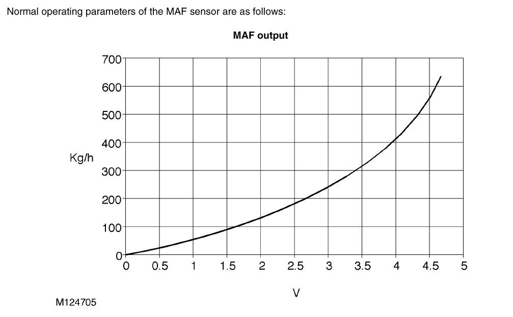
see the graphic and you'll understand that as long as your's is exceeding 5V is not good, there must be a certain correspondence between the voltage and air flow for the management to not be mixed up.
Discovery Td5 (2000), manual, tuned


 Reply With Quote


Bookmarks