

 Reply With Quote
The 5.1 zener might not even open as the MAF output is not supposed to exceed 5V, but if you insist to do these zener tricks connect the anode to a vehicle ground through a resistor not to the ECU's earth path

 Wizard
I didn't use a drop resister as the extra voltage was thought to be less than 0.6 volts. I'd have though a Zener diode could handle sinking 0.6 volts.Originally Posted by disco_ute

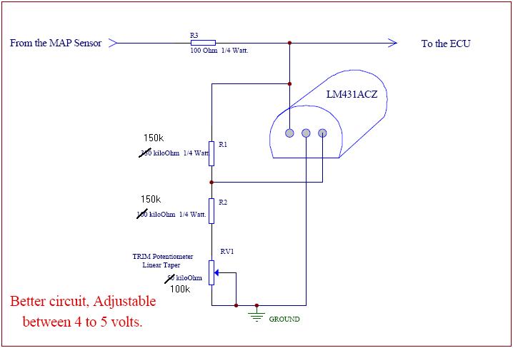
What i will do is put a normal diode forward biased in series with the zener, this will generate 0.6V + 4.7V = 5.3V, but in our case maybe 4.6V. That should work, the normal diode will not be active until the zener is reverse biased. Therefore this circuit should have no effect on the original circuit until it is required.
Still would prefer to try with a 5.1V Zener. Granted though if the Zener fails it is likely to go short circuit so having a current limiting resistor in series with it is a good idea, but it is tricky to calculate the value. We would be better off putting a fuse in, just need to know the max current draw.
Surely we can measure the current draw at max voltage and work backwards to ensure we don't overload the ECM.
YarnMaster
The 5.1 zener might not even open as the MAF output is not supposed to exceed 5V, but if you insist to do these zener tricks connect the anode to a vehicle ground through a resistor not to the ECU's earth path
Discovery Td5 (2000), manual, tuned
Wizard
I tried again with different voltage rating Zener diodes this time, I also put a very low value resister in series with the circuit.
Theory I=V/R
V=5
R=120 ohms
I(A)=0.04A (40mA)
W=0.200 (200mW)
Take 2:
5.1V Zener in series with 120R resistor.
Clamp - 4.7V
Load on circuit - 2mA
Approx. MAF kg/h - 550
Take 3:
5.6V Zener in series with 120R resisitor.
Clamp - 4.9V
Load on circuit - 3.5mA
Approx. MAF kg/h - 670
Measuring the current while testing also proved this modification did not have any affect on the circuit until the breakdown voltage of the Zener had been reached. Therefore you can drive around all day without putting your foot to the floor and the ever so reliable Land Rover electrics will not be affected. (With the exception of you disco_ute with your big turbo, this mod will be active at about 1/2 throttle in your case i'd imagine)
If someone else also could try this to check / confirm my results that would be appreciated. I know you have some great test equipment sierrafery, maybe you could bench test it?
Master
Has anyone found how the maf really works in association with the fueling .I have been talking with some who has been running the maf signal take off the acceleration pedal output and they swear by it . the fact the td5 runs without a maf makes me think that the maf read works within parameters that follow the rpm for ultimate fueling . the argue that some had was that if you do this mod and stomp the pedal it would over fuel. But if the fueling is set to rpm ultimately then all it would do is run as rich as it would without the maf plugged in as that is the most the ECU and fuel map will allow
Master
Supporter
A quick google for FCD (fuel cut defender) which the japs have been using to hot up their turbo carse since the leate 80's, reveals something similar to the above. Pinched that from SoarerWorld forum. WHy cant it be that simple???
Why cant this be as simple as the old "Z32 AFM into the SR20 motor" mod, (google) where the Z32 AFM flows alot more air the the standard SR20 AFM, and can be made to work with the standard SR computer with the aid of a resistor to bring the Z32 readings down to match the SR, but still flowing MORE air.
YarnMaster
I'm up to help but as long as you used higher than 5V zeners and got those voltages it means that your MAF's output exceeded the diode's threshold so it was above 5V which is not supposed to happen with a good MAF but i can't simulate as long as i dont know how much was the voltage before that setup, alos did you connect toi vehicle earth or to the MAF's earth path from ECM?. I forgot few things which might have been discussed as it's a long thread but this cut out symptom used to occur with unplugged MAF too?
Discovery Td5 (2000), manual, tuned
Wizard
I agree the voltage must have been higher than 5V from the MAF, that was the basis of this experiment. But you are correct, i didn't test the voltage until I had the Zener in the circuit. If i were to guess from my results i'd say the voltage was getting as high as 5.2 or 5.3VDC.
The Zener and resistor is between the MAF earth and the MAF output. This is why I believe the clamp voltage is much lower than the Zener, I don't feel the MAF earth through the ECU is 'true'. - It was just more simple to wire this way.
I didn't test for failure without the MAF connected. I assumed the ECU reverted back to the pre-programmed MAP's after the error occurred 3 times in a row. This would explain why it worked eventually if the throttle was held on. Someone else mentioned earlier they disconnect the MAF and they didn't get this symptom.
Wizard
I think this mod is for a different purpose. It looks like the mod is designed so a larger diameter MAF could be used without confusing the ECU in the Toyota.
This is different to what i was trying to achieve.
Wizard
When the MAF is unplugged the ECU refers back to factory loaded fuel MAP's, therefore will not copiously over fuel. If you make the ECU believe it has a MAF connected (throttle output) it will not revert back to the preloaded MAP's.
I'm still not convinced the fuel ratios have much to do with the MAF as logic suggests the Air Temp and Pressure sensor (MAP) would have more influence on the fuel ratio required and considering the car will not run without a crank angle sensor that would suggest the RPM would influence the injector pulses. It could be argued the MAF is used for verification of other know perimeters and potentiality as a turbo over speed sensor.
But last time this discussion was brought up it was in a thread specific to the topic. It would be a shame for it to commandeer this thread and end up the way it did last time. The facts are Land Rover decided the MAF was needed and therefore i feel it should be left in the system, I have chosen to only manipulate the reading in extreme conditions.
YarnMaster
According to your Take 3 if the voltage dropped to 4.9V with a 5.6V zener it means that the voltage was higher than 5.6 otherwise the diode wouldn't have opened so at those kind of voltages i'm 100% convinced that your problem is the MAF sensor and you are fighting to clamp a foobar'd sensor to get proper readings... better drive it with the sensor unplugged than clamp voltages between the output and earth path from ECM cos it's not healthy... at least untill you can rule out 100% the sensor
Discovery Td5 (2000), manual, tuned
 Posting Permissions
| Search AULRO.com ONLY! |
Search All the Web! |
|---|
|
|
|
Bookmarks