Page 6 of 14 FirstFirst ... 45678 ... LastLast
Results 51 to 60 of 134

Thread: LT95 rebuild for beginners

  1. #51
    Join Date
    Sep 2008
    Location
    Geelong, VIC
    Posts
    4,442
    Total Downloaded
    0
    Quote Originally Posted by wagoo View Post
    <snip>
    In the interest of clarity and accuracy I've edited this post probably half a dozen times.Is there any way on these type of technical forums to retain the Edit function, instead of it being disabled the following day?
    Wagoo.
    I don't think so Wagoo.
    I know what you mean, but in general the concept is that the thread evolves from post to post, and editing old posts CAN create a disjointed mess that no longer makes sense (not the case with your edit).
    The other issue is the most people will continue reading a thread from where they got to last time, and not expect the previous posts to change.
    IMHO, a good way is to quote the original post (or part of the post), and make the clarification underneath. That way people can see what the change is and probably understand better rather than thinking "thats not what I recall reading last time"

    When I said that I had to read your post a few times to make it sink in, in hindsight I think the only issue for me was the formatting - that there was lots of info but in a single paragraph - so I had to read it a few times to break it up in my head.

    Anyway - enough of my blathering - back to the rebuild

    Next stage - front output housing.

    Steve

  2. #52
    Join Date
    Sep 2008
    Location
    Geelong, VIC
    Posts
    4,442
    Total Downloaded
    0

    Front Output Housing

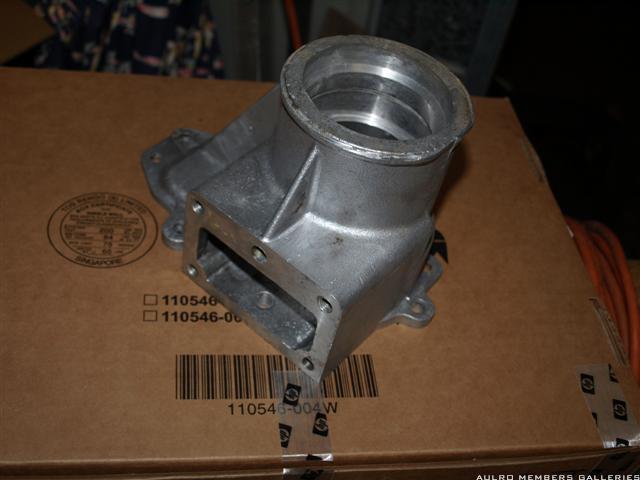
    The front output housing is pretty simple.

    Here's the bare housing - the opening on the side is where the CDL actuator fits:


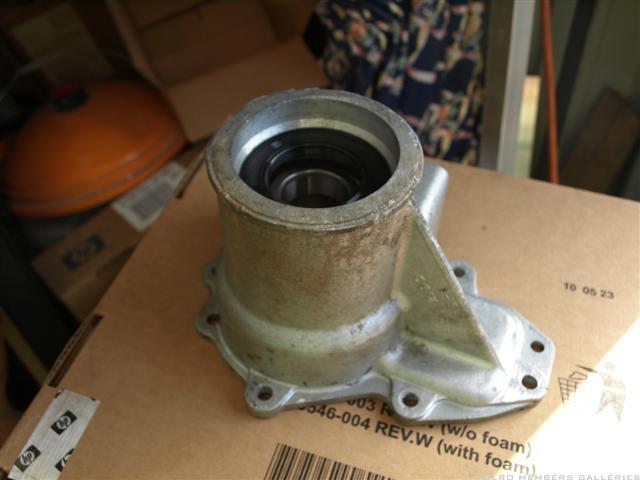
    Just fit the bearing, circlip, and seal :


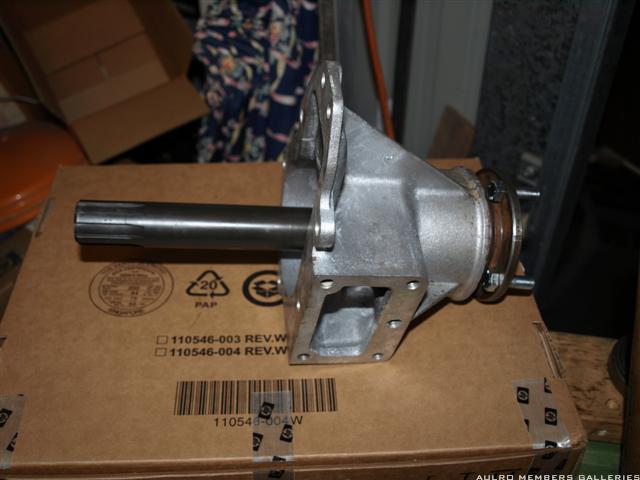
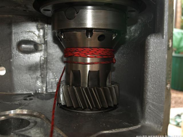
    And then the shaft and flange. Use some form of sealant under the washer to stop any oil leaking down the spline (I used some loctite 518). No need to put it all down the splines - just under the washer.
    If you need to replace the flange bolts then you will need to press off the mud slinger ring from the flange first, and refit it after fitting the new bolts.

    Also, don't forget to refit the 2 dowels into the mounting flange if you removed them.

    All assembled (minus the dowels) :


    Steve

  3. #53
    Join Date
    Sep 2008
    Location
    Geelong, VIC
    Posts
    4,442
    Total Downloaded
    0
    As a side note, the front output flanges are the same on all RRC and 110 LT95's. The only one that is different is the Stage1 box which has much larger flange since it had a double cardan joint in the front shaft.

    In my case both of my boxes are from Stage 1's. Since its going into a 110, all I had to change was to remove the Stage1 flange and fit a flange from a 110/RRC LT95.

    Steve

  4. #54
    Join Date
    Sep 2008
    Location
    Geelong, VIC
    Posts
    4,442
    Total Downloaded
    0

    Center diff bearing preload

    Although I'm still waiting on parts for my center diff, now seems like as good a time as any to set up the preload on the center diff bearings.

    Fit the rear bearing cone to the assembled diff - making sure that it is fully home against the shoulder (it goes a couple of mm further than flush with the end of the diff).
    Fit the high range output gear, and front bearing cone. I found it easier to leave the low range gear off the diff at this stage as it allows you to get your fingers around the side to hold it as you fit it into the housing.

    With the case vertical (rear of the case uppermost), lower the diff into position in its forward bearing like this:


    The next part of the procedure in the manual says to sit the rear output housing (speedo housing) in place without the gasket, and measure the gap between the housing and the case.
    Take into account the gasket thickness, then adjust the preload to 0.05mm by fitting the appropriate size shim behind the bearing cup in the output housing. It suggests to fit the original shim as a starting point, and work from there.

    I've tried to do that and I reckon the procedure sucks.
    The concept is OK, but the practicalities of trying to measure with feeler gauges etc to 0.05mm, on a ~250mm diameter disk that can rock slightly unless you keep steady pressure on the bearings just doesn't make it easy.
    Surely there has to be a more practical way.

    Since there aren't any shafts etc fitted at this stage (only the diff itself), is there any reason you cant set it up in a similar way to the layshaft bearings - ie just sufficient preload to get a slight increase in the force it takes to rotate the diff?

    Steve

  5. #55
    Join Date
    Oct 2010
    Location
    Dixons Creek Victoria
    Posts
    1,533
    Total Downloaded
    0
    Having spent a lot of time rebuilding diffs for a living I just sort of developed a feel for preload resistance without instruments, and would do as you suggest with a bit more resistance for the centre diff than the layshaft due to the diff having larger bearings.

    I've always reckoned that there are not enough bolts holding the rear output housing onto the case.(The Japs would use twice as many) so on occasion if the client agreed I would drill and tap a few extra holes around the bottom half of the housing.
    Wagoo.

  6. #56
    Join Date
    Sep 2008
    Location
    Geelong, VIC
    Posts
    4,442
    Total Downloaded
    0
    I bolted it up with the gasket just to see what it was like. Definitely took out the "spinning freely" feeling that it had before I bolted it down, but going by the feel of the layshaft, it needs just a touch more.
    I've got some gasket paper thats just a touch thinner than the current one, so I think I'll just make one up, fit it and see how it feels. Will measure with a spring balance just for something quantitative.

    Quote Originally Posted by wagoo View Post
    <snip>
    I've always reckoned that there are not enough bolts holding the rear output housing onto the case.(The Japs would use twice as many) so on occasion if the client agreed I would drill and tap a few extra holes around the bottom half of the housing.
    Wagoo.
    Why just around the bottom half? Just to keep it clamped well from a leaks perspective?

    Steve

  7. #57
    Join Date
    Oct 2010
    Location
    Dixons Creek Victoria
    Posts
    1,533
    Total Downloaded
    0
    Quote Originally Posted by steveG View Post


    Why just around the bottom half? Just to keep it clamped well from a leaks perspective?

    Steve
    I knew you would ask that.Around the bottom half has the desired clamping effect to reduce oil sweating through when hot. Extra bolts around the top half as well may be better and easy to do during the overhaul stage, but just makes it a little more difficult and time consuming to access all the bolts when later servicing the centre diff in the vehicle with the hand brake assembly still fitted.
    Wagoo

  8. #58
    Join Date
    Sep 2008
    Location
    Geelong, VIC
    Posts
    4,442
    Total Downloaded
    0
    Well, I made up the slightly thinner gasket (.05mm thinner) and bolted it up.
    Just a nice feeling preload now. A little bit of drag but can be turned with a finger and thumb around the high range gear.
    Using a spring balance its a nice smooth 3kg to keep it moving with the string wrapped around like this:


    Thats roughly the same force as the layshaft preload, but considering that its on a larger diameter shaft (about 70mm compared with 50mm on the layshaft) its a slightly higher torque.

    Think I'll leave it at that.

    Steve

  9. #59
    Join Date
    Oct 2010
    Location
    Dixons Creek Victoria
    Posts
    1,533
    Total Downloaded
    0
    Another tip I just remembered ,(Sorry ,its been 5 years since I last worked regularly on landRovers and my memory is on drip feed) On hard worked and abused vehicles, it was found that the output housing bolts required regular retightening to reduce weapage. After a while the threads in the alloy housing would wear and sometimes strip.Replacing the bolts with studs and nuts is one way of addressing the issue while providing greater clamping force.What I found easier and possibly better was to buy bolts 13mm longer and plain nuts.Run the nuts all the way up to the head of the bolt.Screw the bolts all the way into the housing, then tighten the plain nuts against the output housing.I never had a bolt work loose after doing this, although there was still some weepage until I drilled and tapped the extra bolt holes mentioned earlier.
    Wagoo.

    Edit, Just noticed on the photo of your transfercase that the second selector shaft detent ball is about to escape.

  10. #60
    Join Date
    Sep 2008
    Location
    Geelong, VIC
    Posts
    4,442
    Total Downloaded
    0
    Quote Originally Posted by wagoo View Post
    ...
    Edit, Just noticed on the photo of your transfercase that the second selector shaft detent ball is about to escape.
    I might LOOK like its about to escape, but its not going anywhere
    Spent about 15 mins with magnets, WD40 etc trying to get the sucker out when I disassembled the box. It must have a burr on the edge of the hole that's preventing it coming out, and since the spring is still good behind it I figured I'd just leave it there.

    Good info on the bolts. With normal bolts, is there any benefit in using loctite on the threads, or some form of sealant on the gasket?

    No problem with the drip feed info. I'm trying not to move on from each section too quickly - for exactly that sort of reason.

    Steve

Page 6 of 14 FirstFirst ... 45678 ... LastLast

Bookmarks

Bookmarks

Posting Permissions

  • You may not post new threads
  • You may not post replies
  • You may not post attachments
  • You may not edit your posts
  •  
Search AULRO.com ONLY!
Search All the Web!