

 Reply With Quote
Ooooh, the N O I S E

 ChatterBox
Plenty engineered with 35's in NSW...
Stefans D2 is probably the most engineered that I know of and very well documented. Treeve does his work.
Master
SupporterOoooh, the N O I S E
Master
SupporterI did a bit of a search and came across a video where Treeve was testing some defenders with 35" tyres. If forwarded them to my engineer to see if that will sway him. Thanks for the suggestionOriginally Posted by MR LR

It is nice. Though pretty obnoxiously loud!
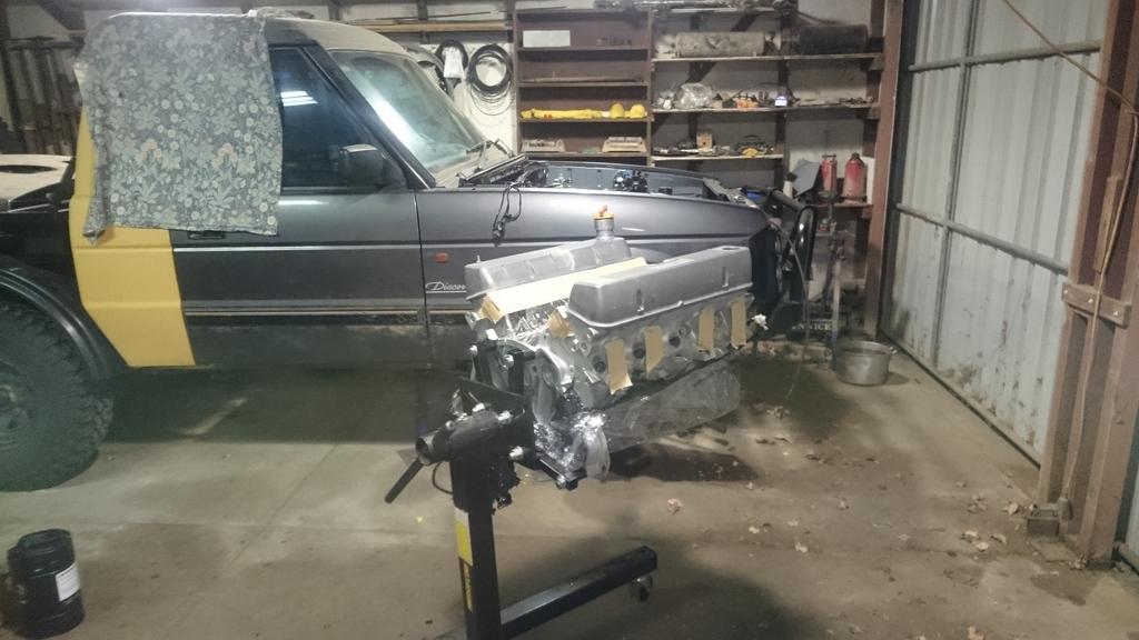
Anyway, just a quick update from my hotel room in Italy, I just arrived to go to a meeting tomorrow. I'll be back in Australia on Sunday night.
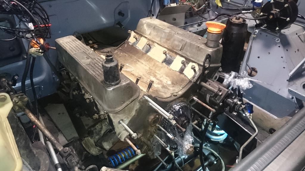
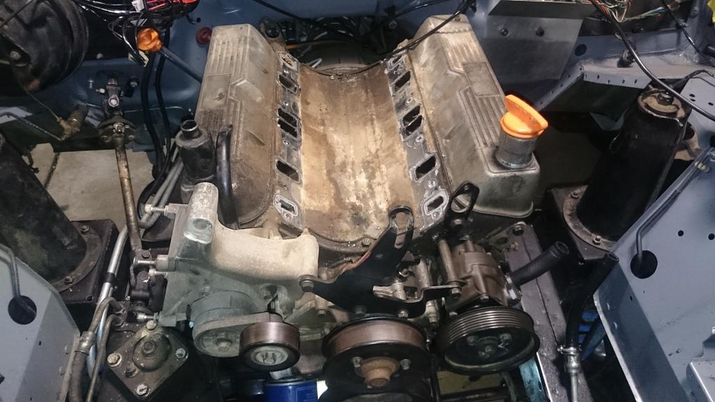
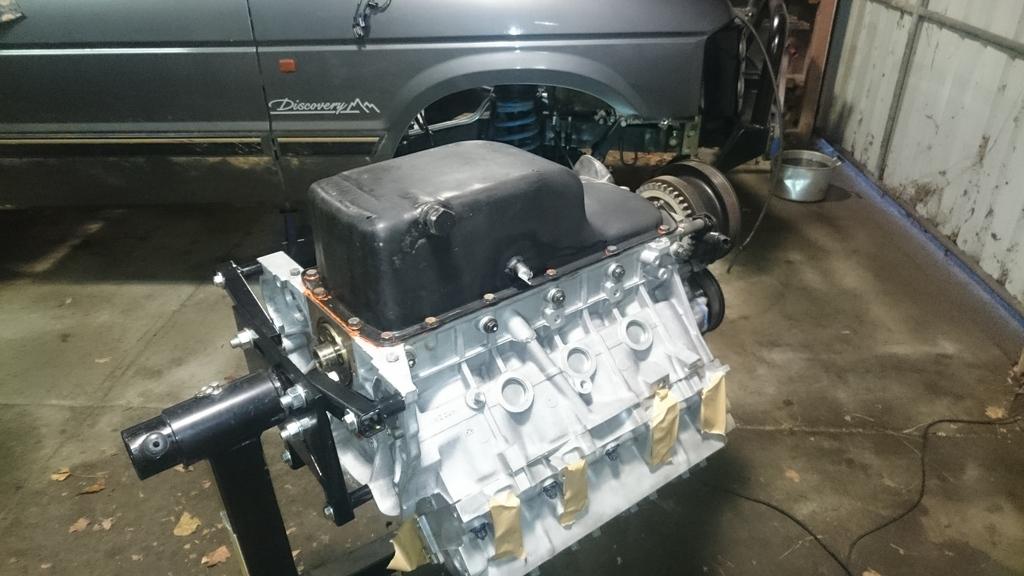
By the end of last weekend, the engine was basically completely prepped for removal. Just two bell housing bolts hold everything in place.
This is the benefit of running on LPG. Everything stays pretty clean!
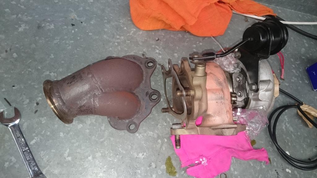
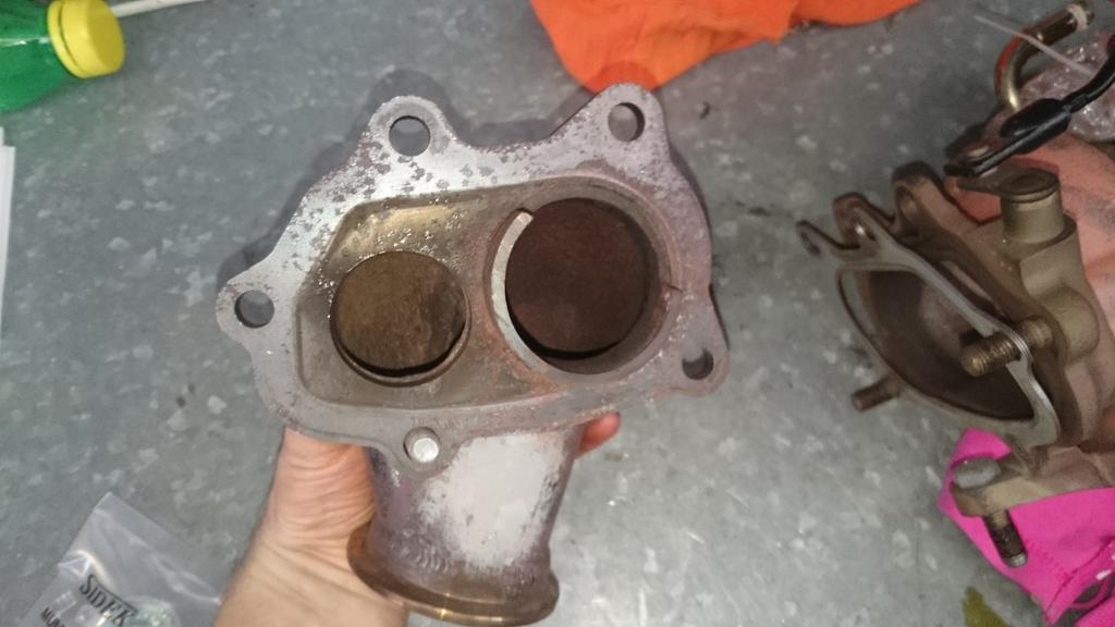
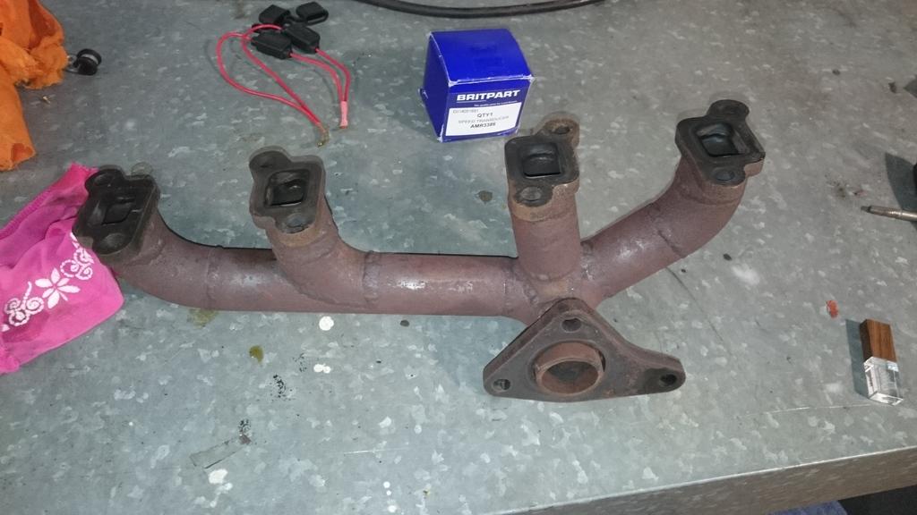
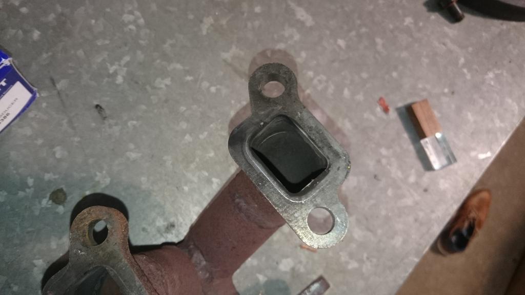
My manifolds & dump pipes are well on their way to getting a healthy layer of corrosion. I think I'll resort to getting them ceramic coated, though I would like to find someone that will do it on the inside as well. If anyone has some suggestions, let me know!
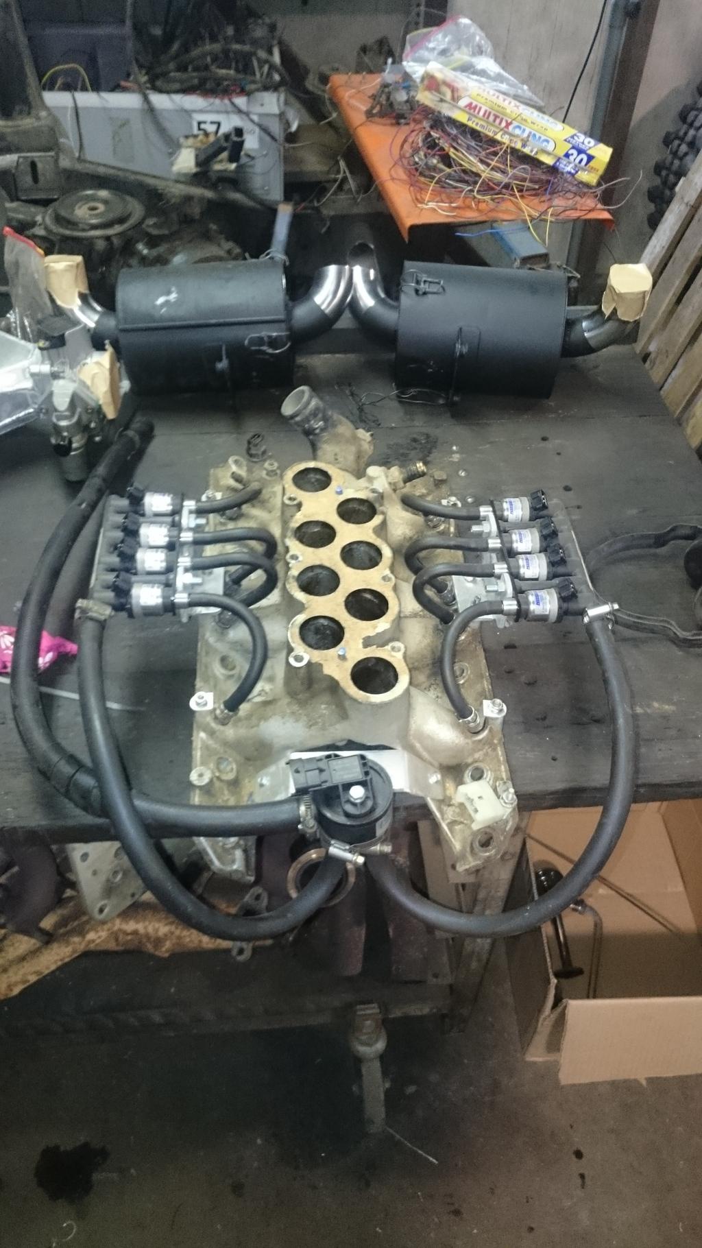
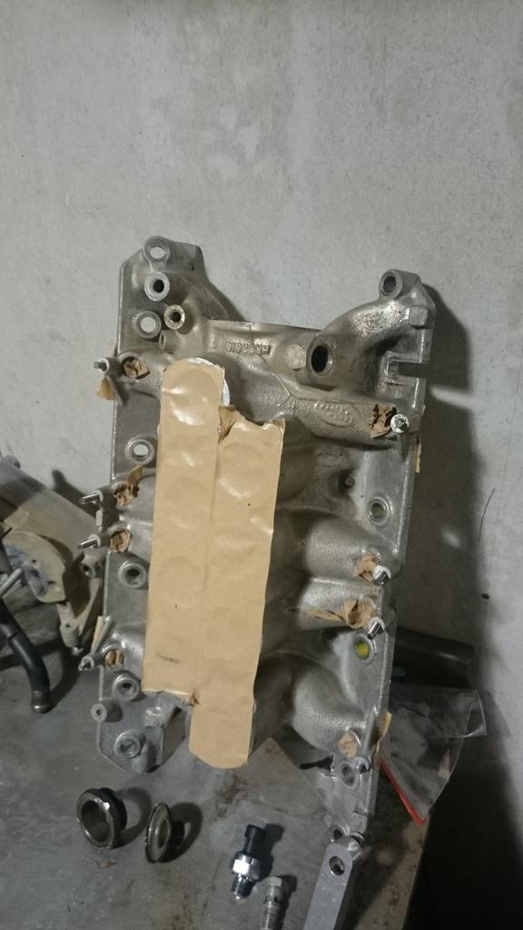
Inlet manifold off, and after the photos below, the injectors were removed so that the manifold can be cleaned up.
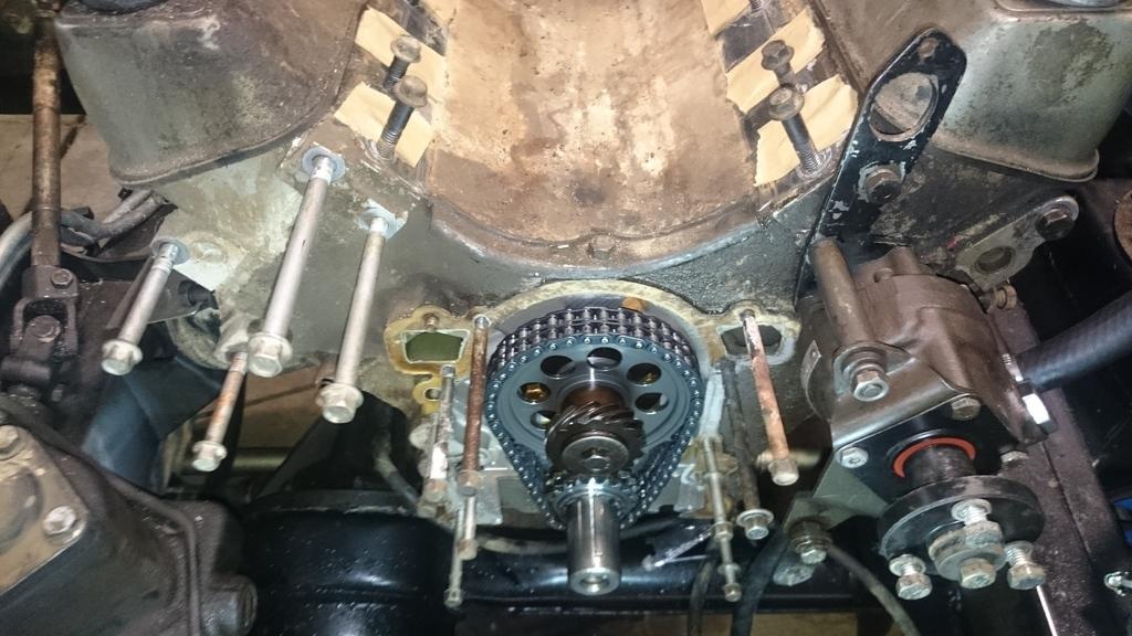
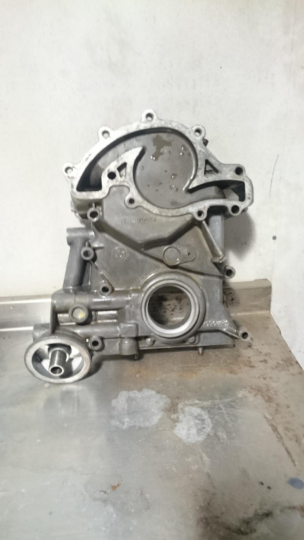
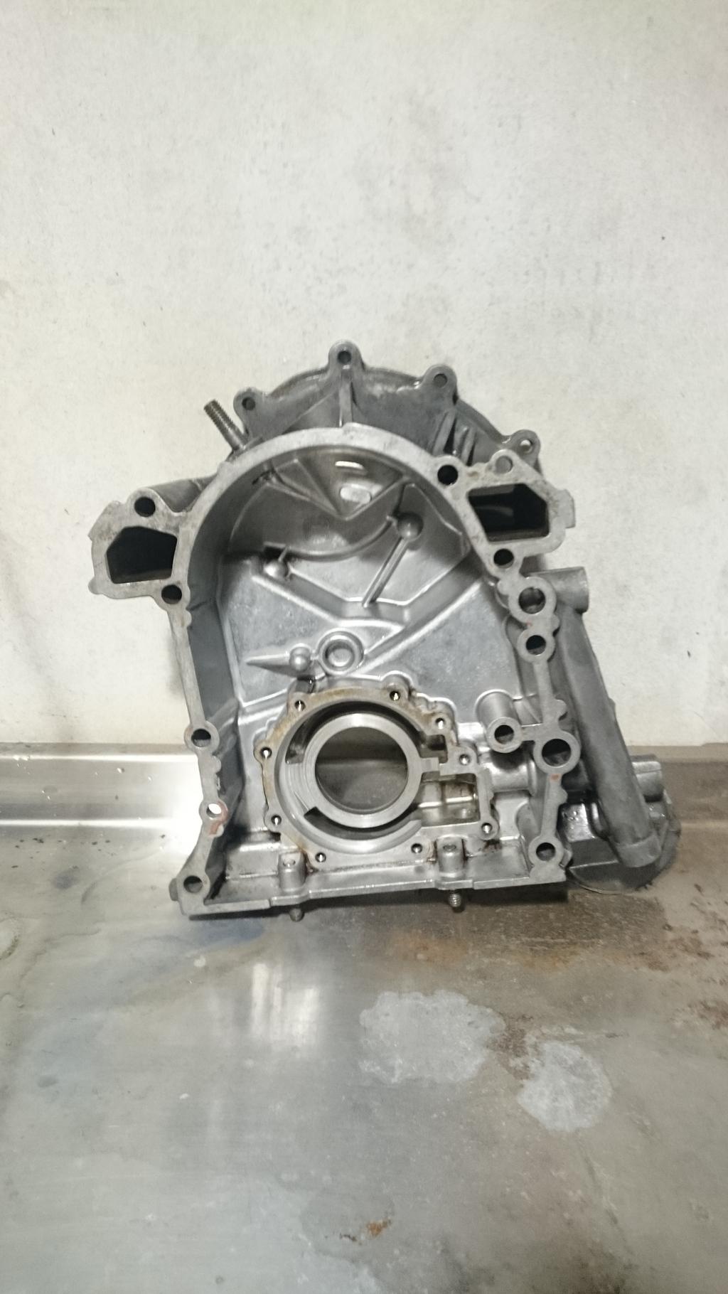
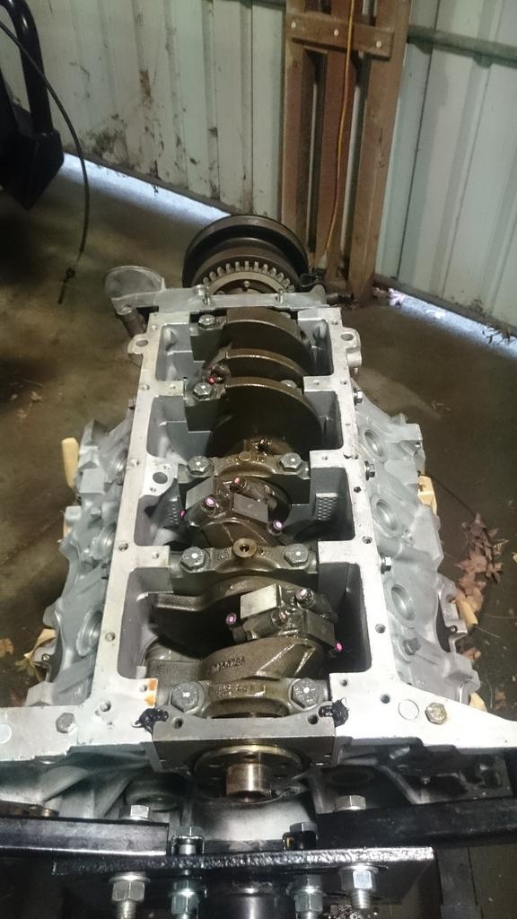
Timing cover off. I had forgotten that this engine had a rollermaster timing chain and gear set.
This is something I definitely wasn't expecting to find. Some fairly deep gouges onto the oil pump plate, I had a look at the gears and they appear to be installed correctly, I wonder if they are on backwards? Or if it is simply due to the wider chain?
And this is where it was all left.
Stirling
Master
SupporterOh, by the way, I'm seriously considering grinding off all the hot water passages off the intake manifold and re-building something independent of the manifold to minimize heat transfer. Crazy idea?
Stirling
Master
I know of one other person that had the timing chain issue you have on a 3.9V8 turbo. And it caused a lot of damage to his turbo (all the fine metal). He had to go back to the standard single timing chain
ChatterBox
That's well known with the Rollmaster chains. You just grind off what's in the way. It's easy to check with Blu Tack or similar. No need to use a single chain.
At any given point in time, somewhere in the world someone is working on a Land-Rover.
Master
SupporterHello again everyone, time for another brief update.
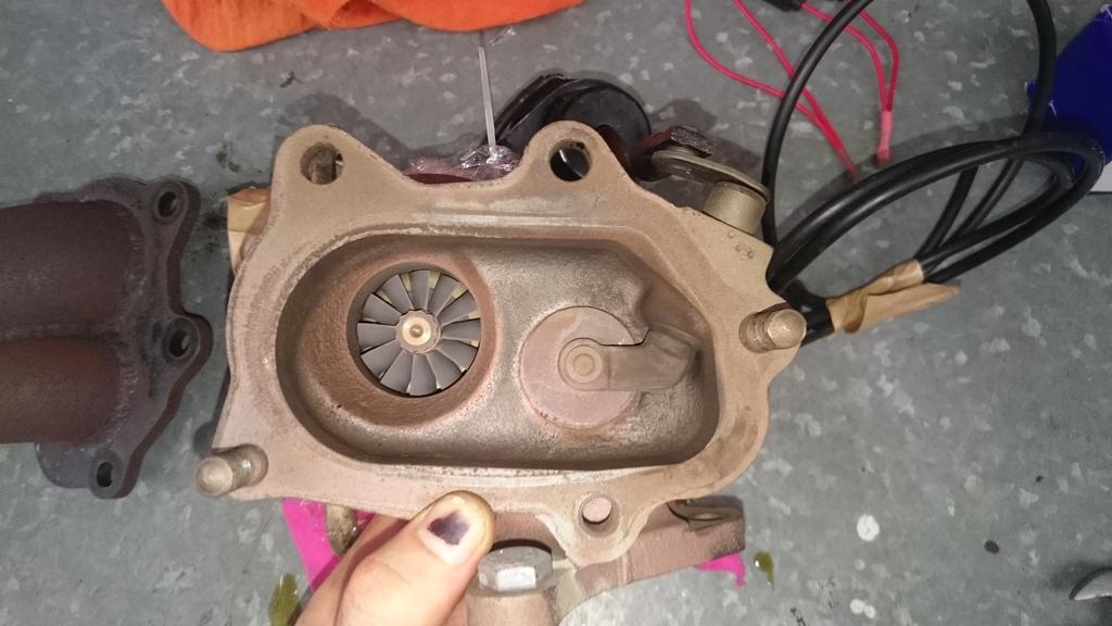
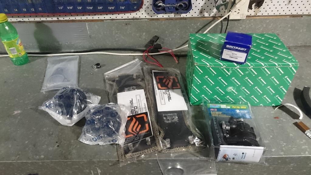
So i've been doing some shopping... Turbo blankets, some Jaguar V12 engine mounts and a Davis Craig electric pump - which will hopefully be better than the chinese Bosch knock-off pump I tried before to circulate coolant through the turbo casings.
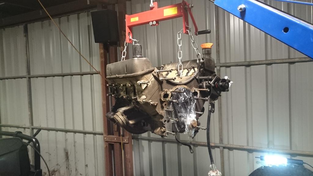
The engine was extracted.
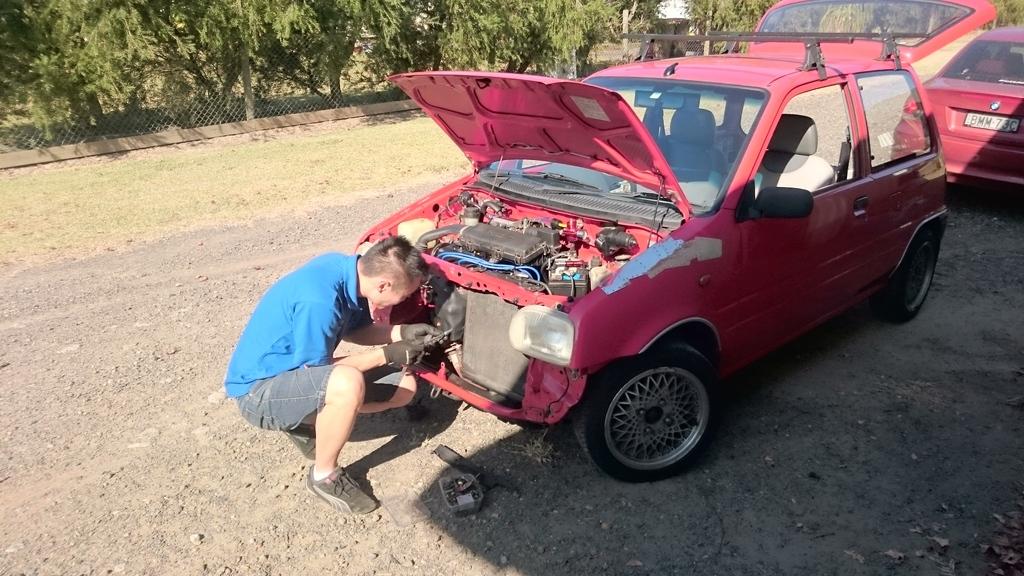
Over the weekend Derrick swung by for a visit to do some work on his $300 Daihatsu Mira, which by the sounds of things is on a path to donning a turbo charger soon
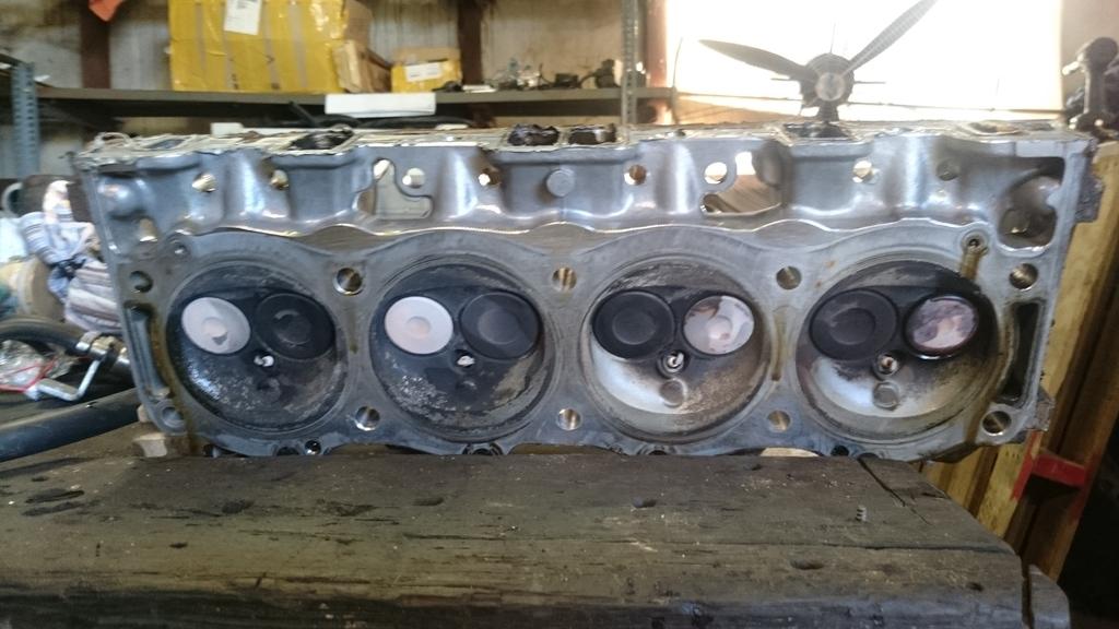
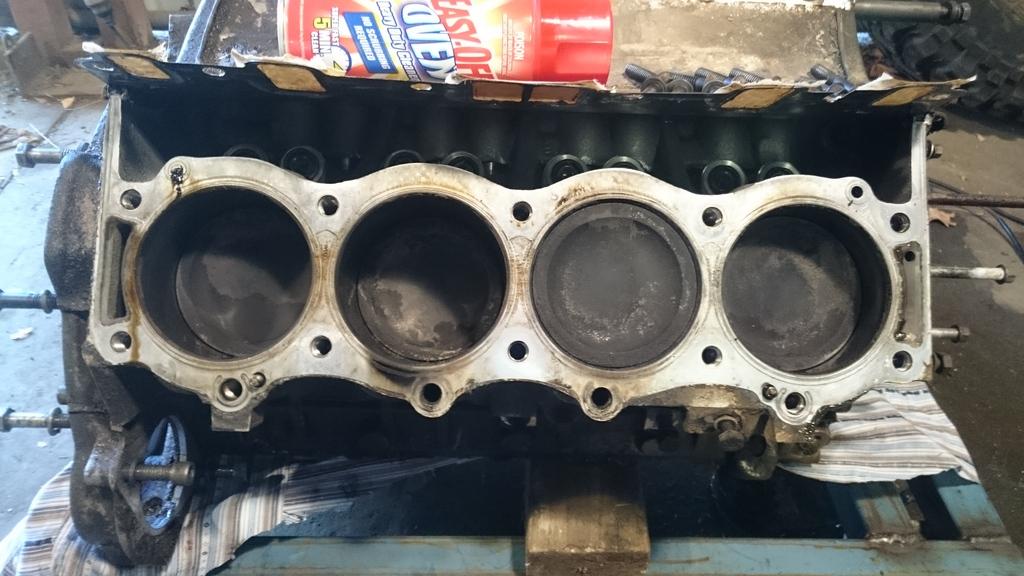
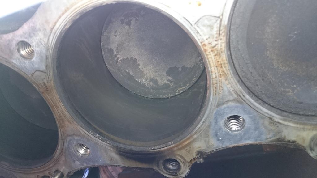
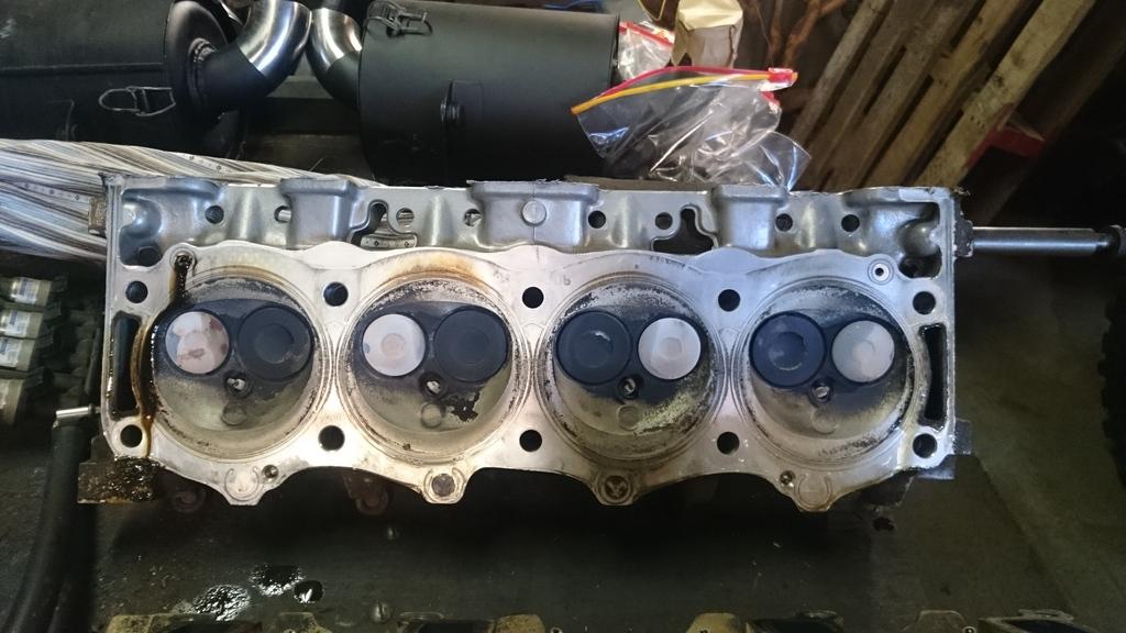
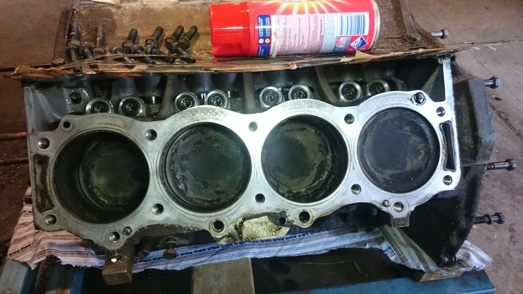
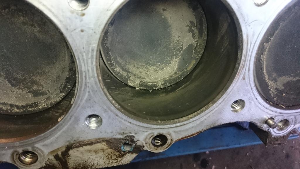
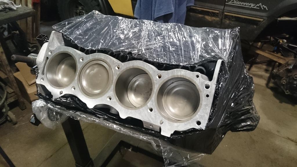
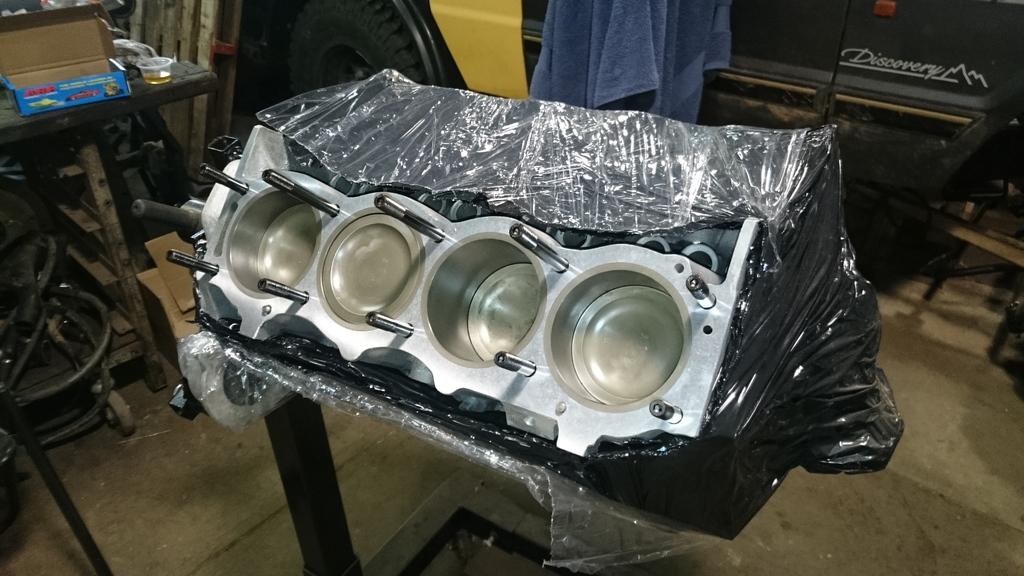
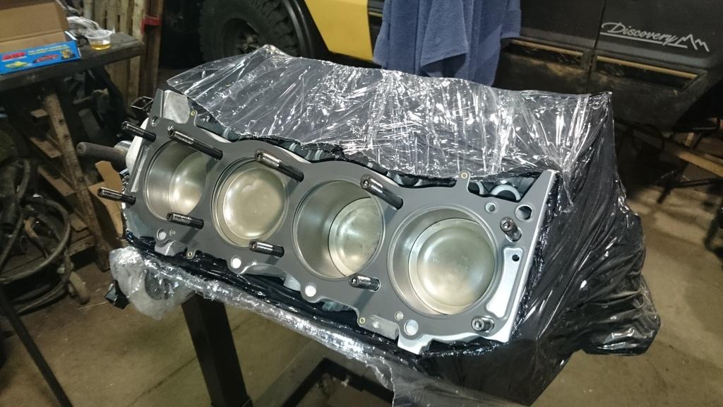
Some shots of the engine after the heads came off. A few cylinders leaking! That may or may not be a result of when I took the car for a drive with no boost control enabled... From memory I got to 20psi of boost or something like that. If anyone wants this block when I'm done, drop me a line.
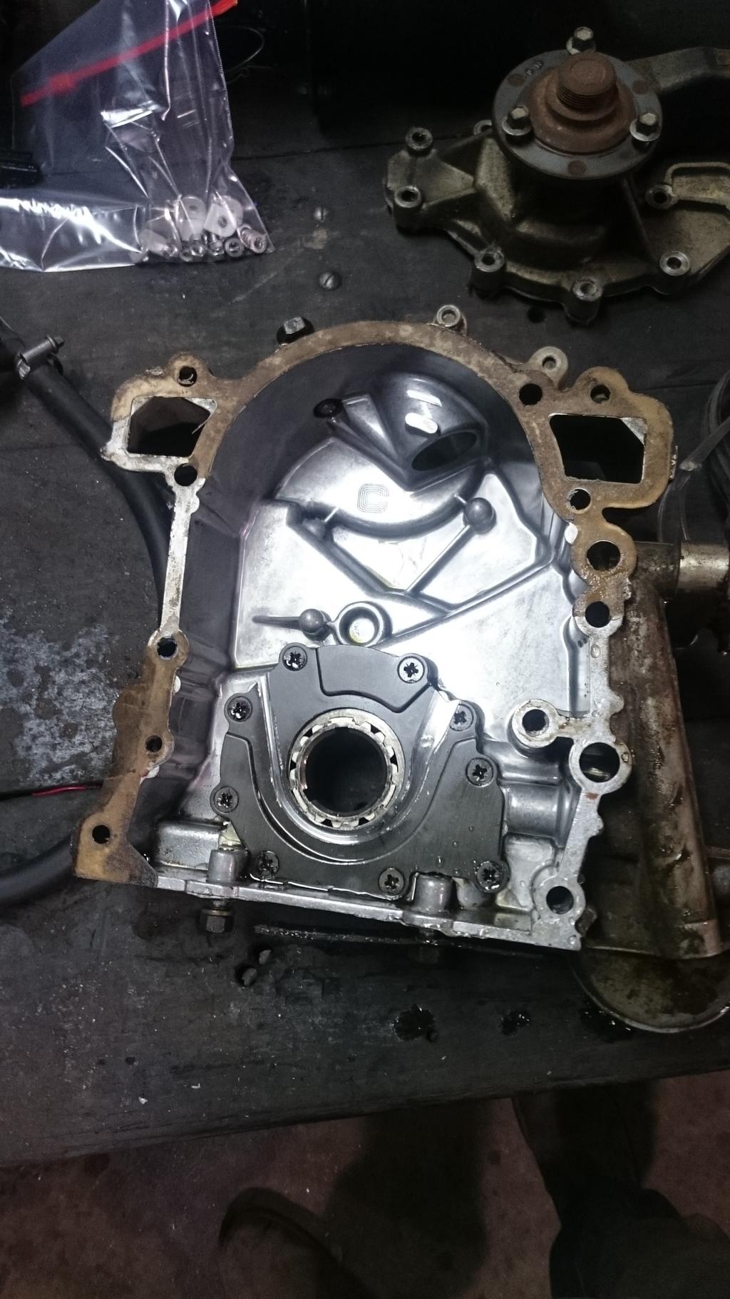
And then I finished the day with some therapy. Cleaning the old timing cover and sump with oven cleaner. Came up pretty well I think! The sump... well, I got a little too carried away with the high strength oven cleaner and damaged the paint, I don't think I will worry about it though, the last place you find rust on a land rover is on the sump, thanks to the liberal coat of oil it gets over time!!
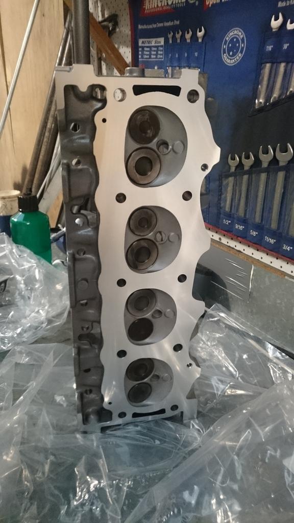
The cylinder heads are at the moment at an engine re-conditioner to be checked over, overhauled and put together with some higher rate valve springs. If all goes well, the cylinders will be bolted onto the new block this weekend! I'm keen to see what the new block looks like!
Stirling
Master
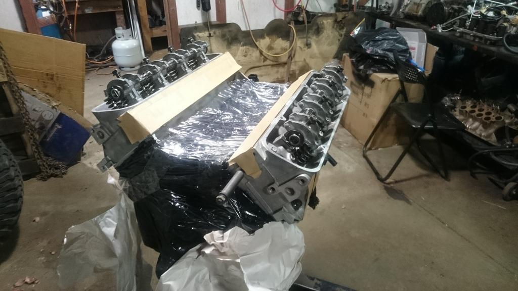
SupporterMore progress on some shiny bits!
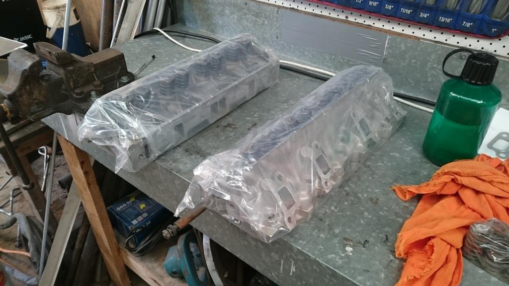
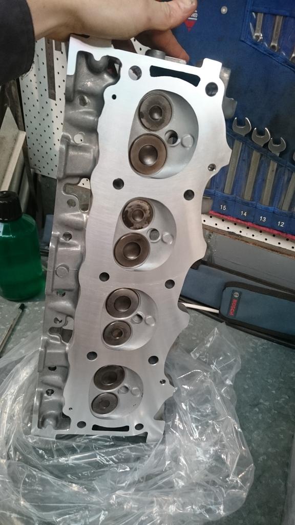
Cylinder heads came back after being overhauled.
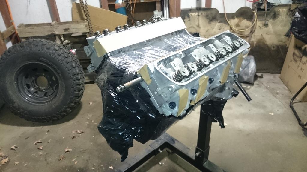
All the bits to get the heads bolted onto the block
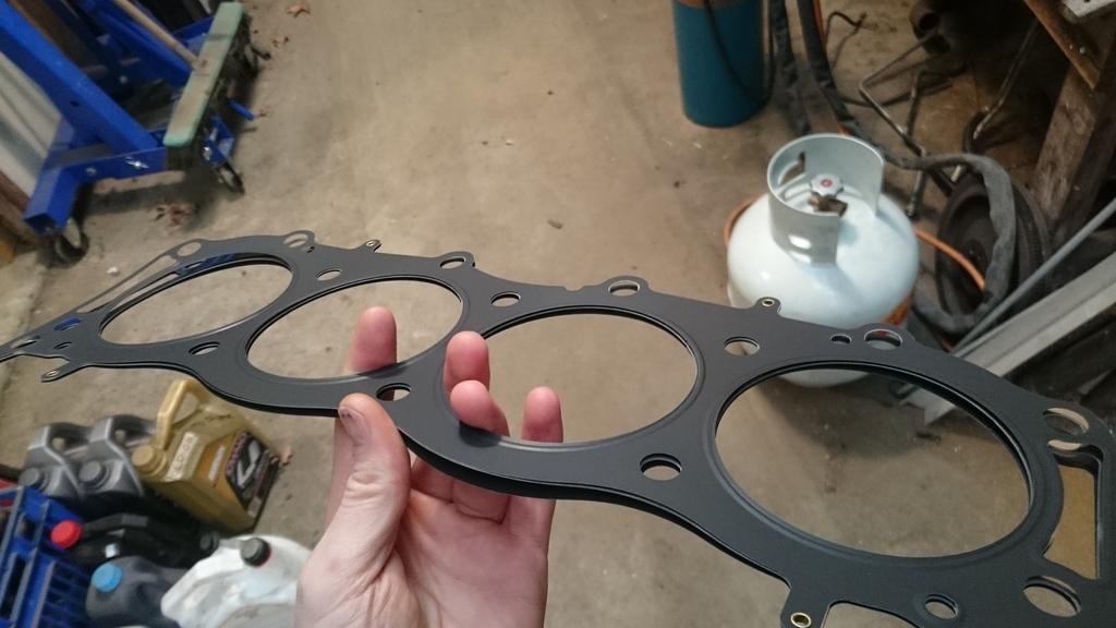
The gaskets used were recommended by the guys at Triumph Rover Spares, as you can see it is a multi layer gasket which should hopefully hold up.
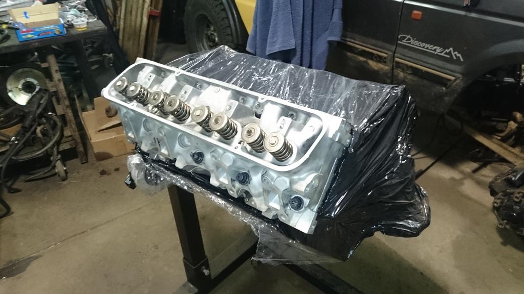
And the process of installing the studs, gaskets & heads. All going together pretty easily. I ended up torquing down the heads to 135Nm as per the stud kit instructions (about 100 lb-ft).
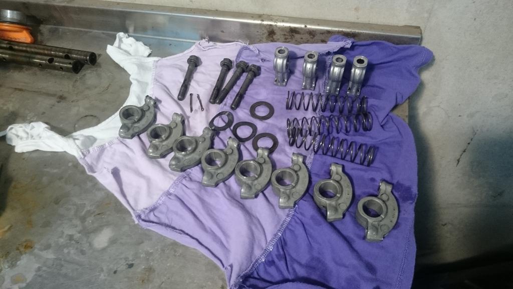
Next was cleaning up the rocker assemblies. The shafts didn't have all that much wear on them, but I bought some new shafts anyway. Below is how nicely the water based degreaser cleaned everything up. I quickly ran some 1200 grit sand paper through along the circumference of the rocker bores. I remember reading somewhere that this is important to sand back any embedded stainless steel in the aluminium and allow the shafts to last a little longer.
The rocker assemblies were put back together.
Next step is to check the hydraulic lifter pre-load, I ran out of time so that will be for another day.
In the mean time the exhaust manifolds and turbo dump pipes have been sent off for ceramic coating. I decided to go this way to reduce the corrosion of all the hand made parts. I really don't want to have to build them again... If I do, I will do it out of stainless next time!
Stirling
Master
SupporterHope no one got flooded with all the rain that went down the east coast this weekend!
I was busy trying to push on with this build.
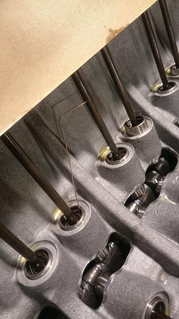
After completing the rocker shafts it was on to shimming them to ensure I had the right hydraulic lifter clearance. RPi Engineering has excellent article on how to do it here:
RPi Engineering - Specialized Rover Engines - faqs
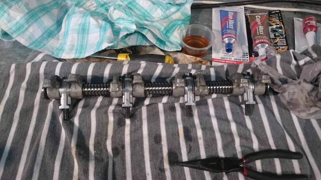
I ended up needing to shim up the rocker shafts between 1.2 and 1.5mm from the heads to get the preload between 0.02" and 0.06". Some mig wire hit a couple of times was perfect as the 0.02" feeler. And a TIG filler rod served as the 0.06" feeler.
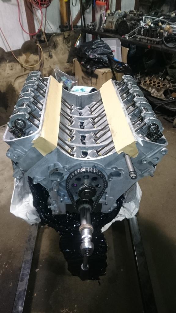
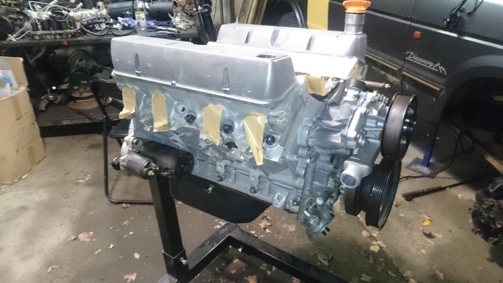
The full set completed and rocker assemblies torqued on.
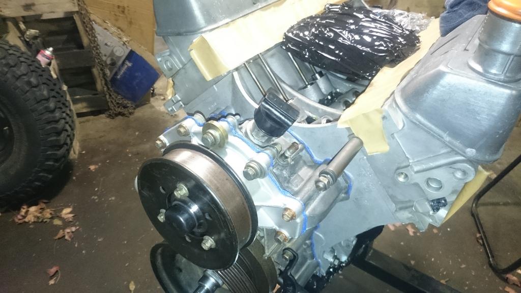
Timing cover on.
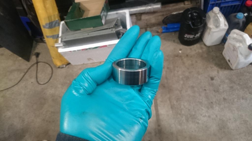
For this engine I am using a timing cover from a 3.9L engine as it was all modified already to hold the York compressor, the large alternator and coil packs. The 4.0L crank is longer than the 3.9L so a bush is needed to hold the crank pulley in position.
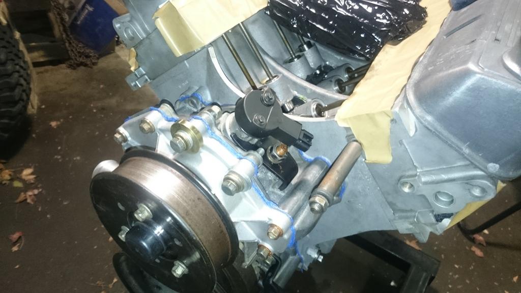
Installing my home made cam position sensor with the right phasing to the crank position sensor.
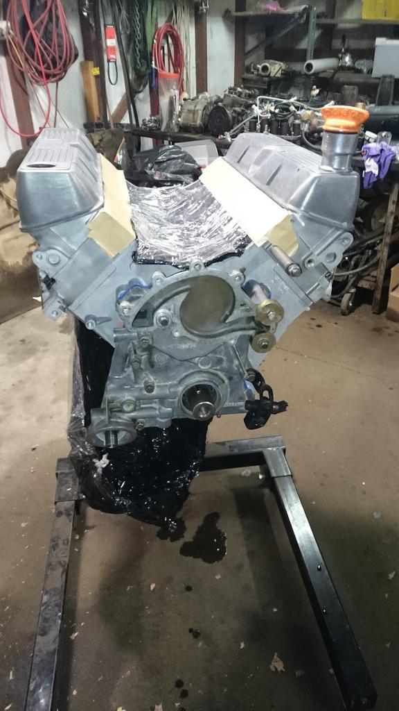
Sump was put on. I opted to install it without a gasket and simply use a gasket compound. These engines notoriously leak from this area so I degreased everything in the hope that I can avoid any weeps later on (I'm not holding my breath though). And yes - I did fit the oil pickup line, in case you were wondering...
After giving the starter motor a light external clean up (trying to avoid getting any water and degreaser into it), it was bolted on.
The intake manifold was cleaned up. I pulled out the 8mm pipe fitting that was on the side. When some barbs arrive I'll drill out the hole to fit a 16mm barb for the LPG evaporator and then fit the 8mm barb onto the side which was the original cabin heater takeoff point.
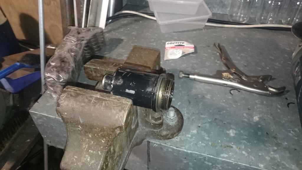
I've decided to run two crank case breathers, so I'll be welding on a threaded nipple onto the oil filler point of the tappet cover and the photo below is the beginning of modifying the original crank breather. I'll hopefully be able to finish this when the threaded nipples arrive so that I can weld everything up.
Till next time!
Stirling
Master
I see a Ford cam sync sensor there.
 Posting Permissions
| Search AULRO.com ONLY! |
Search All the Web! |
|---|
|
|
|


Bookmarks