

 Reply With Quote
Update from last weekend's tinkering.
Gussets are in... They were a bit on the fiddley side!
Anyway, holiday time now (or in 3 days anyway). Stay posted for more progress on my return!

 Master
Supporter
Master
SupporterI'm back!... For a while.
I got in to the workshop today with the plan of finishing off the 16 flanges and getting the beams tack welded into position. A highly repetitive task considering I had to drill out alllll the holes and then run the tap throught them! And then all the tidying up to get rid of burrs and the like!
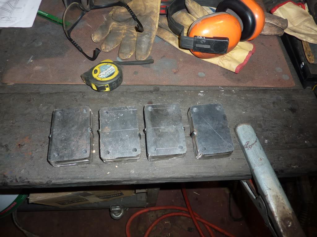
4 groups of 4 plates welded together and drilled out:
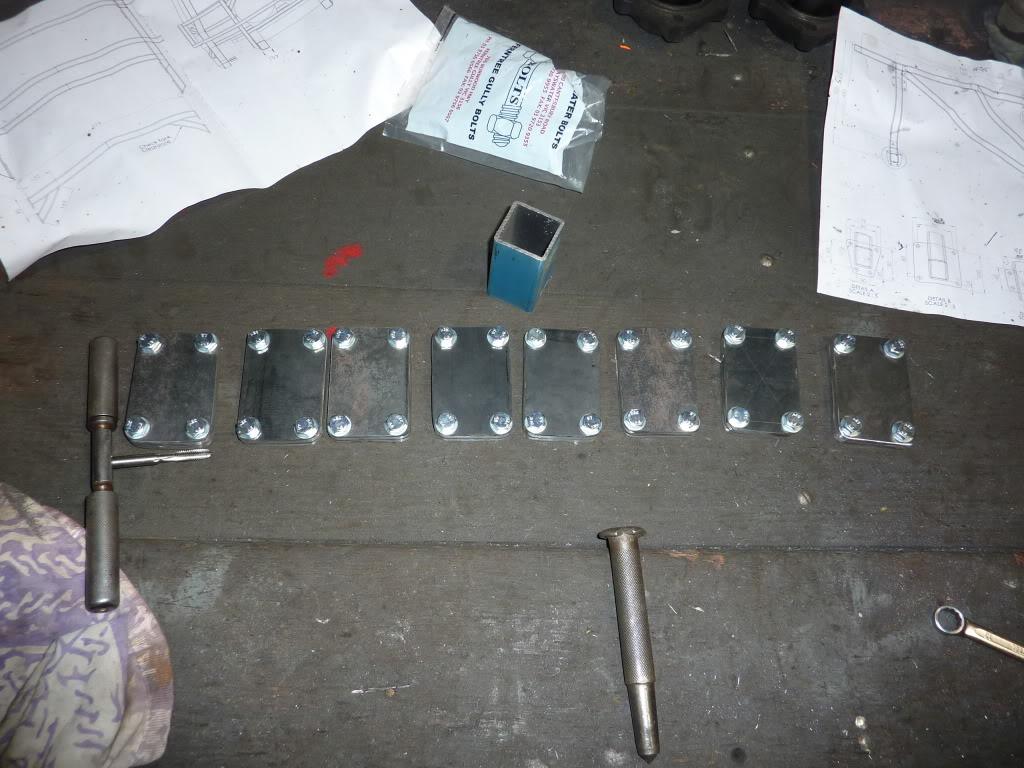
All the hole tapping done:
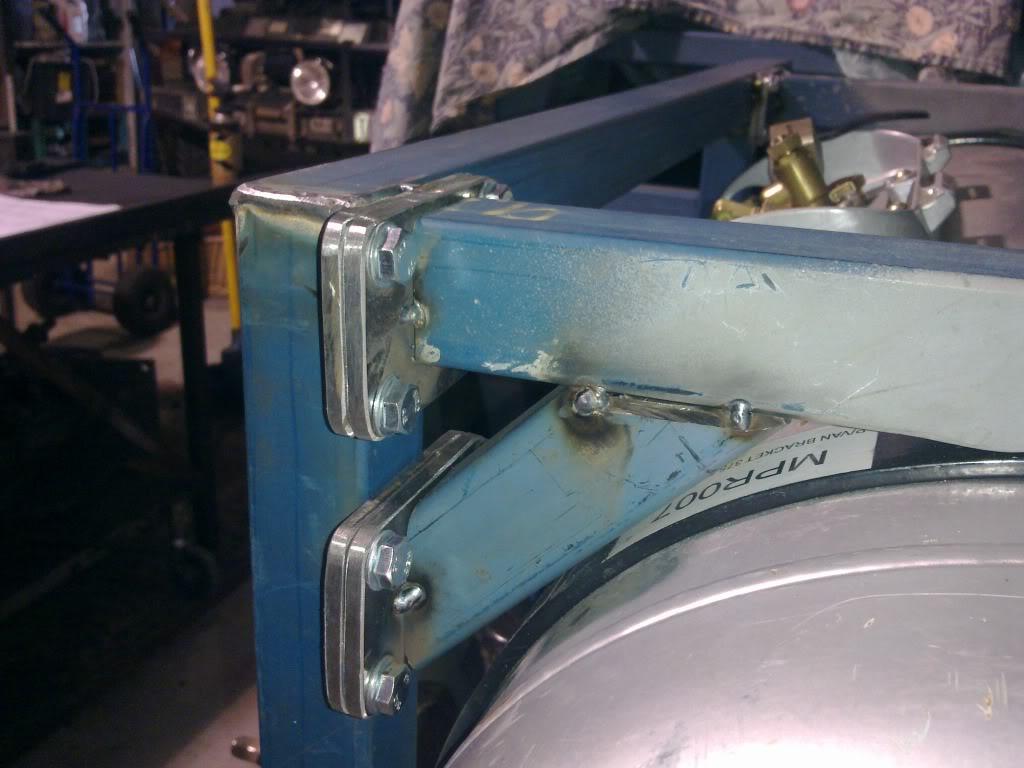
And to finish up, the flanges for the horizontal beams were tacked in!:
Next time will be a bit tricker, as I need to cut the gussets for the 4 corners to stiffen up the frame.
I plan to get another day of work in next weekend. Following that I will be away for a 3 week holiday in Europe
Stirling
Master
SupporterUpdate from last weekend's tinkering.
Gussets are in... They were a bit on the fiddley side!
Anyway, holiday time now (or in 3 days anyway). Stay posted for more progress on my return!
Stirling
Master
SupporterWell, i'm back again. I had an excellent holiday, if anyone is curious
Right, back on topic. Does anyone know what happens when you go in to the workshop at 10:30am on Saturday and then don't leave until 3:30am the next day??
The answer is: Excellent progress!
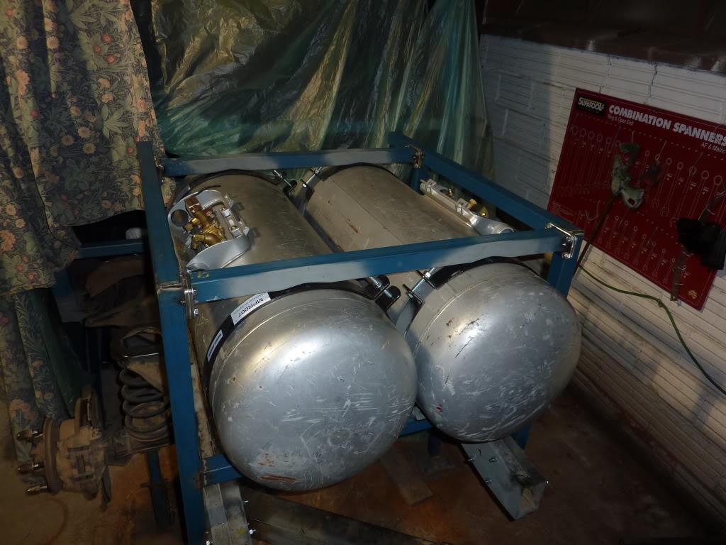
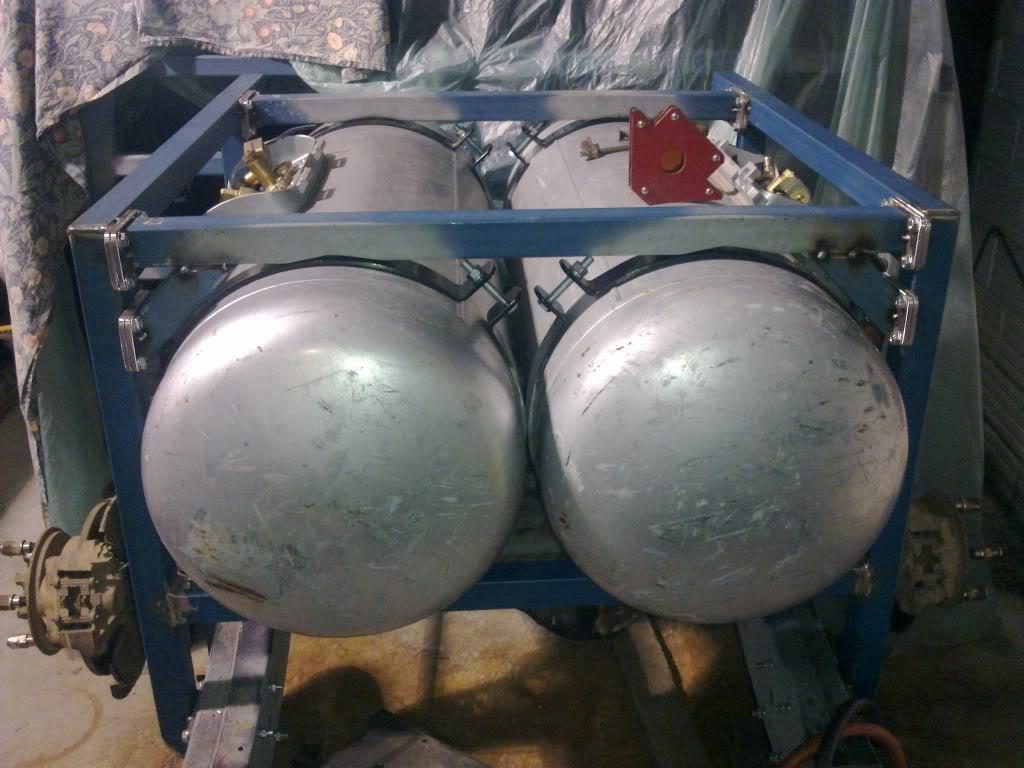
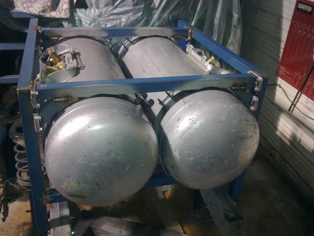
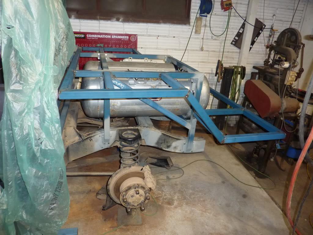
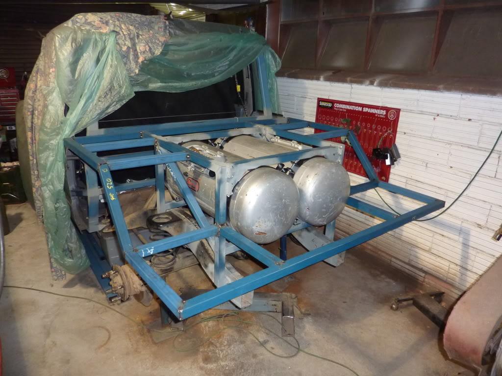
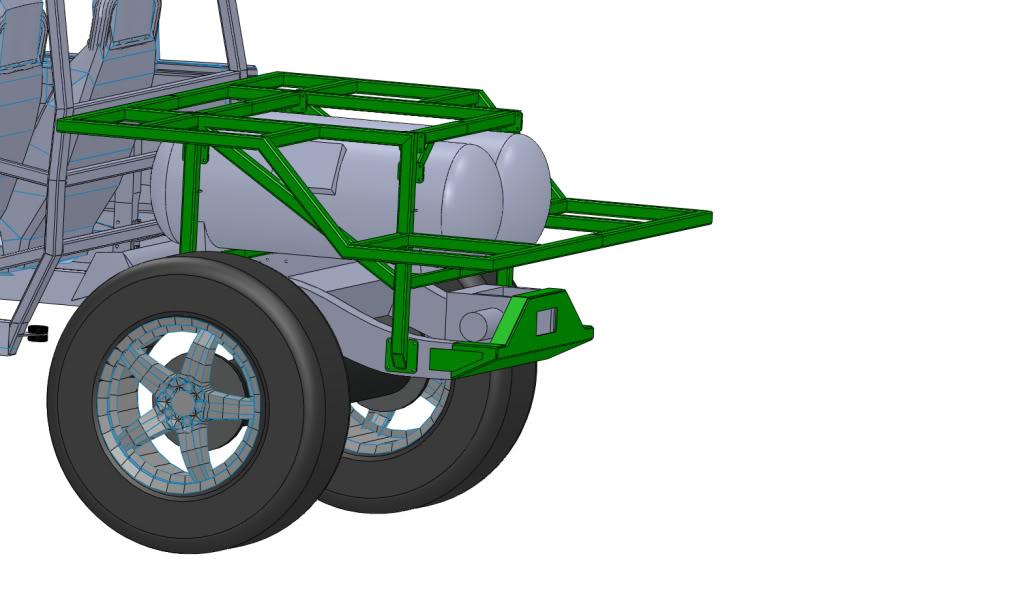
Welded in the diagonal braces to stiffen the inner frame in the longitudinal direction and bolted the tank brackes onto the inner frame:
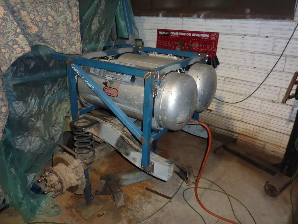
I then pulled the frame off the car to reach all the welds which I couldn't reach with it on the chassis.
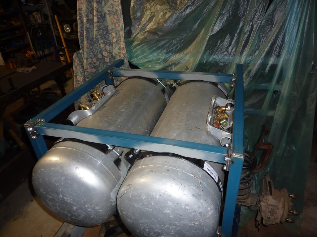
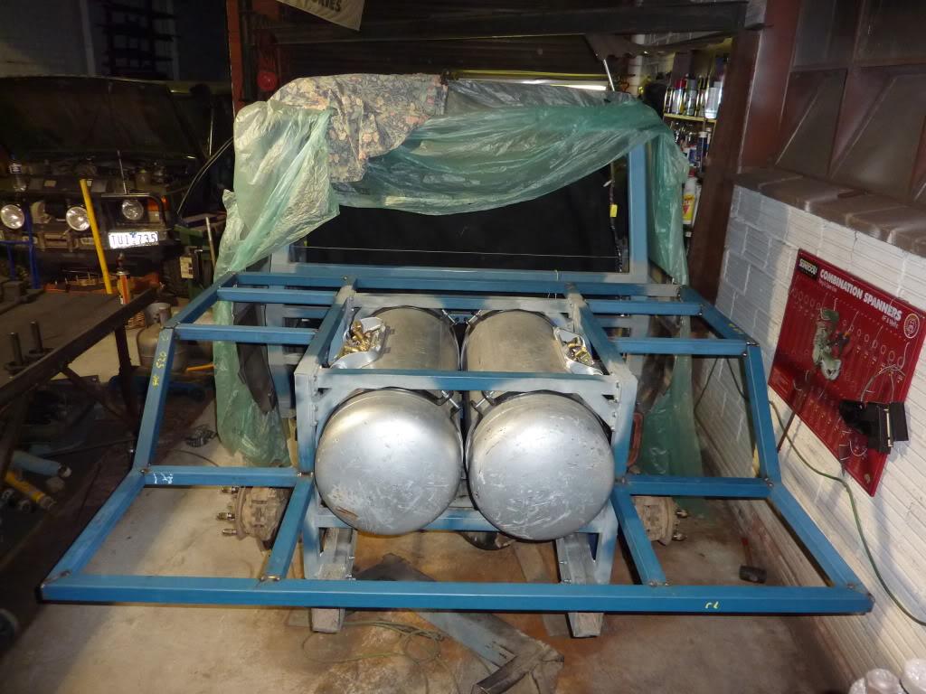
Then, after many hours of work, ALL of the external frame members are cut and tacked in place:
I'm happy with the way it has all turned out, and it looks like everything ended up aligning correctly with only an error of a few mm here or there.
Next week i'll go back and weld up all the joints. I now have to start thinking about that rear winch mount!
Stirling
ChatterBox
SubscriberOutstanding
Conventional wisdom seems to suggest whacking those right angle corners off the rear and having angles there instead. Looking at them, might they be prone to being bent out of shape without bracing?
Just a thought. Great to see it coming along, from one of those who have *not* had a holiday
Alan
Alan
2005 Disco 2 HSE
1983 Series III Stage 1 V8
Master
SupporterThanks for the pointer there Alan. You are right that the corners do seem a bit light in the structural department. And when compared with the middle and front of the tray, they certainly would be weaker. However, I think they may be strong enough since the steel is 3mm wall and it will have a 5mm thick aluminium surface fixed onto it.Originally Posted by disco2hse

My old land rover's tray was basically entirely made from aluminium and I had slammed it against a few rocks and trees in my time and it never deformed.
I'll ask the engineer when I arrange him/her to come and do an inspection of the framing to see what they think
Stirling
Master
SupporterUpdate again,
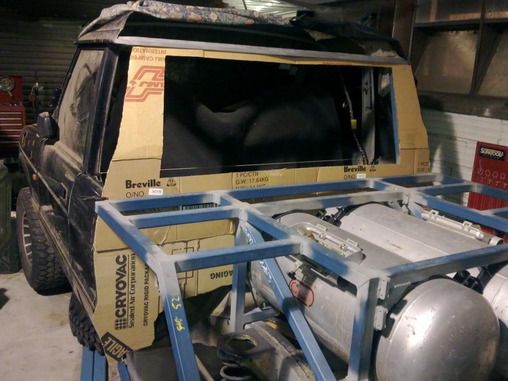
Tray frame is all welded up (as of 2 weeks ago). And then last weekend I cut out a rough cardboard template of the rear wall profile so I can now go to wreckers and see what rea wall will suit best.
End of the update.
Stirling
Master
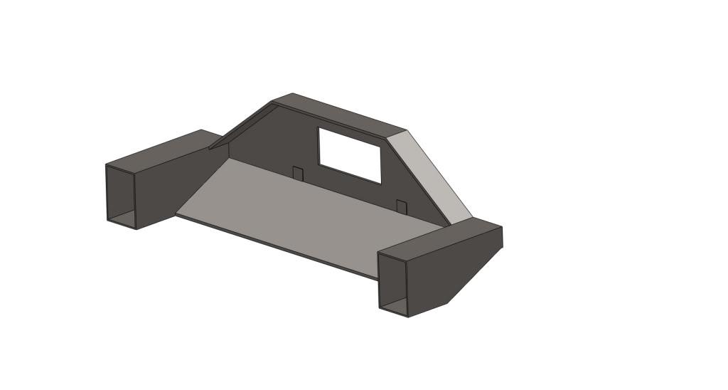
SupporterTonight I was doing some more design work. I had a few hours free to do the work.
I was working on the design of the rear winch mount to see what would fit reasonably well and came up with the following concept built from 5mm plate:
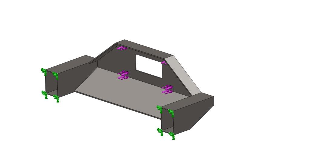
I figured that since this assembly is going to take a fair amount of load, that I should do a structural assessment of the assembly to make sure it would be up to handling the loads that could eventuate in use. So I built a model to do a Finite Element Analysis (FEA) of the design:
I applied the boundary conditions, I figured a decent starting point was a load directly backwards of 100,000N which is just over 10 tons on the winch mounting points. The reason I chose 10 tons is I figured that would be about the expected shock load you could get from a snatch or a 9,000lb winch. Below are the loads applied:
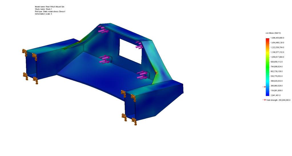
And got the results, the deformation shown is magnified by 5 times:
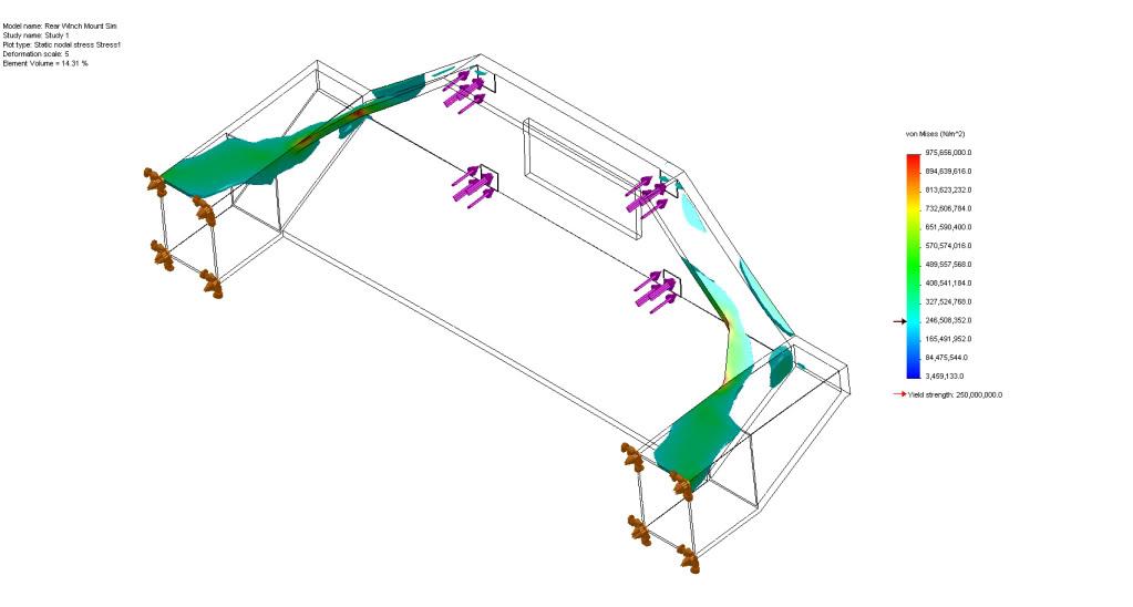
Based on the above, the design fails. The main area is in the corner as you can see in red where there is a stress concentration. So I added some 50mm gussets in this region and got the following results:
The above is better, but it still fails in a lot of the areas. Light blue are above the yield stress of steel (you can see it on the bar graph). So it looks like I will need to re-design the part with 8mm steel (or maybe 10mm?) and see if that would be up to handling these loads. But that will be another day's job.
Stirling
TopicToaster
Have you modelled the chassis? I doubt that is made of 5mm or 8 or 10mm for that matter. I know that the forces are not tangential on the chassis but at what stage do you start to rip the holes with the fastners?
Master
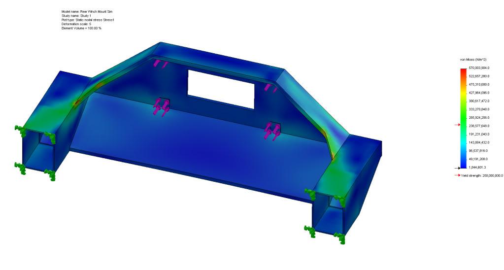
SupporterYes I have, the exposed ends of the model are 3mm thick steel which is what the chassis is made from. You will see the step where it goes from 5mm to 3mm in the image below.
Anyway, I spent some more time on the model to see what I could do to minimize the stress in the part. The wall which the winch was mounted to was increased to 8mm and the stiffening that runs over the top and down to the rails was increased to 10mm. I even radiused various areas to reduce the stress concentration that created. Unfortunately that still wasn't enough. Below you can see all the areas which are above the yield stress of the steel.
I then reduced the applied load from 100,000N to 60,000N and get the following results:
I tried a few other stiffening methods, however it is proving to be very difficult to get the stresses all over the part to be under the yield stress, even with a load of 60,000N. I think I'm going to have to ask my house mate who is a structural engineer to see what his suggestions are.
Unfortunately due to the shape of the winch I don't have many areas where I can add stiffening!
Stirling
TopicToaster
By the shape of the winch comment I take it you cannot increase the size of the gusset to that in the violet or even the red below?
Increase the material yield strength, use a bisalloy with a higher hardness?
Use a doubler plate as per the yellow?

 Posting Permissions
| Search AULRO.com ONLY! |
Search All the Web! |
|---|
|
|
|
")


Bookmarks