
Originally Posted by
windsock

I was quoted AUD500+GST for a new motor via winch industries. Freight would have bumped it up another AUD50-75 I guess. Rate of exchange on top of this, well, not cheap whatever way it is looked at like you say.
I think that works out at the same from Pan Pacific, maybe a bit more.
Do you mean drift it out with the gear on out through where there would be a seal? The pinion gear is approx 35mm diameter. Or do you mean drift the motor shaft out off the gear? I was afraid to wack it too hard in case I broke the aluminium gearbox housing.
Definitely not a good thing to break the casing. Once the bolts that hold the motor in place are removed the only thing holding it onto the casing is the gear on the motor output shaft. This is removed by carefully sliding the gear off the end of the shaft. The method for doing that is what is referred to as drifting which means you apply even and measured pressure on at least three points around the gear and pull it off. I was able to do it with just my fingers but it required some leverage to get it started.
I think it might also be a case of previous owner assuming the wrong problem. I still have that new motor if required.
")
Hah. Good score 
Kind of hard to describe an maybe I should scetch out a few things for my own sake so I don't over over-engineer

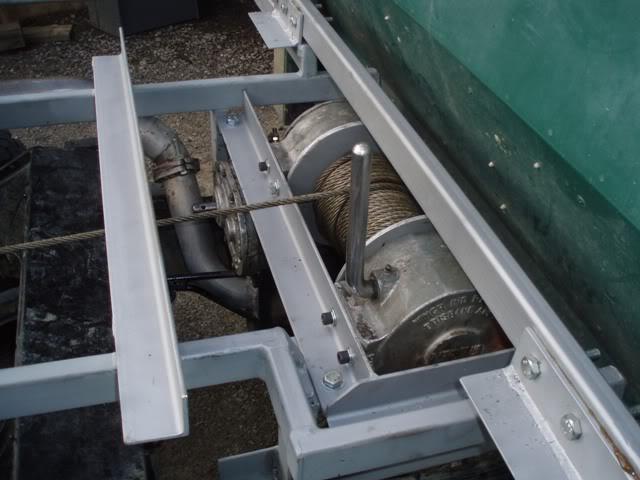
I intend to be able to see it spool up under load from the drivers seat byway of the rear window so I can keep an eye on it. The first run of rope out from the winch will basically be the full distance from the head of the tray to the rear and so it should spool in layers nicely without bunching up. Time will tell whether theory reflects the reality...
Would really like to see some pics when it is done, while it is being done
Sounds like you will have a great set up.
Cheers
Alan
Alan
2005 Disco 2 HSE
1983 Series III Stage 1 V8


")

 Reply With Quote
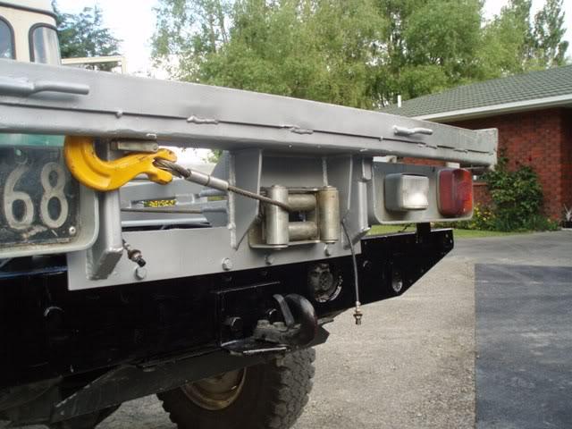
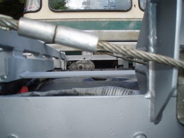
 Once this was undone and a burred shaft was cleaned up the gear virtually fell off...
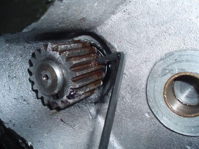
 It now sits slightly higher than the bottom edge of the rail and means the muffler is not continually getting whacked, bent, and buckled.

Bookmarks