Page 3 of 4 FirstFirst 1234 LastLast
Results 21 to 30 of 40

Thread: Comparison between 2.5" and 3" exhaust

  1. #21
    Tombie Guest
    Quote Originally Posted by Benny_IIA View Post
    well the op has posted more info then I have ever seen posted by td5 alive who claim there is no power gain just that your turbo is going to over speed and destroy it self.

    I would be very interested to see your dyno graphs showing the results for different systems.

    No worth much. But I picked my 90 up from the exhuast shop today where I had it fitted with a 3' straight through system and it had no increase in boost pressure over the standard system which had cat fitted. Turbo is a stage 3 TT vnt though.

    That coupled with the dual airbox's and uprated intake hoses made a massive difference.
    Sounds like a nice upgrade!

    The TT Stg3 is a 3" quoted (by TT) unit and rated to it.

    The smaller units are not, and based on the say so of TT only rated to 2.75" pipe.
    This was discussed and quoted in depth in a post long ago. Including compressor maps and data including the statement about overspend by Garrett themselves.

    I've given up sharing most of what I know lately as honestly I find it often tiring...
    Just as I gave up making gear - it was no longer enjoyable to do.

    I don't expect people to care or understand. So I just do my thing on here and if you don't like it... Fine by me.

  2. #22
    Join Date
    Jan 1970
    Location
    'The Creek' Captain Creek, QLD
    Posts
    3,724
    Total Downloaded
    0
    See pages 336, 337 & 338 in Turbocharging the Internal Combustion Engine by Watson and Janota. The parts of Section 9.5 on these pages are worth reading for their relevance to this thread.


    Note in Figure 9.21, the effect of exhaust system back pressure on Turbine inlet temperature (EGT or exhaust gas temperature) and Specific Fuel Consumption. The EGT results are self explanatory, SFC is how much fuel the engine requires to produce a unit of power per hour. Lower SFC means lower fuel consumption or more power from the same fuel.

    Unfortunately the egt results given in the original post are affected by different ambient conditions when they were recorded. If the ambient conditions were the same, the lower egt would be consistent with the results for lower exhaust back pressure shown in Figure 9.21.

    With the rise in use of jet turbines, etc. after WW2, the knowledge and development of turbo machinery was extensive. Much of the knowledge is applicable to turbochargers.

    The power/torque required by the compressor must be supplied by the turbine and is a function of the turbine plus mechanical efficiency, the mass flow of the exhaust gas, the gas temperature at the turbine inlet, and the pressure ratio (or if you like the expansion ratio) across the turbine (i.e. TIP / TOP).

    For example, if the required pressure/expansion ratio is 2.5 and the TOP, equal to the exhaust back pressure is 2 psig or approximately 16.7 psia at sea level, the required TIP is 2.5 x 16.7 = 41.75 psia ~ 27 psig. If the back pressure is reduced to 0.5 psig ~ 15.2 psia, the required TIP would be 2.5 x 15.2 = 38 psia ~ 23.3 psig. During the engine exhaust stroke a considerable amount of power is lost due to the piston acting against the pressure in the exhaust manifold (TIP). Another side effect of the higher TIP is an increase of the mass of residual exhaust gas in the cylinder during the inlet stroke.

    So it is beneficial to reduce the TIP – this is reflected by the curve for SFC vs exhaust back pressure in Figure 9.21. BTW 0.05 bar ~ 0.73 psi and 0.2 bar ~ 2.9 psi.

    Exhaust back pressure increases with gas velocity and reduction in diameter. As pipe diameter is increased the back pressure reduces, but above some point the returns diminish rapidly and further increase of diameter is of little worth for the engine speed used during normal driving.

    Referring to Figure 9.22 on page 338, the recommended upper limit for exhaust back pressure is 0.05 bar (0.73 psi).


    IMHO 3" would be worthwhile for a turbocharged 4BD1. If it was simple (it is not IMO) I would go bigger for my own compound turbo 4BD1T.

    To realise the benefits of a free flowing exhaust system discussed here, the turbo and waste gate setting need to be matched to the engine. The waste gate is the appropriate device to use for regulating turbo speed and inlet pressure, not a restrictive exhaust system as some might be inferring.

    Too many use a small turbo that produces boost at low engine rpm, then create excessive TIP by tightening the waste gate in an attempt to get boost pressure that is off the compressor map without knowing what is going on. A turbo from a TD5 at 25+ psi on a fueled-up 4BD1 for a classic example.

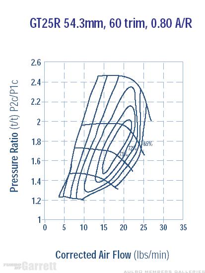
    For an inter-cooled 4BD1 at 2200 rpm, 20 psig boost pressure (PR 2.4), and 0.7 compressor efficiency, the compressor will require approximately 25 HP to produce the mass flow of about 18.9 lb/min. The exhaust velocity will be approximately 242 ft/min in a 3” pipe or 348 ft/min in a 2.5” pipe. To produce the power required by the compressor the PR for the turbine will be about 1.84 at an egt of 650C.

    At 2600 rpm, 25 psi boost (PR 2.7), and 0.7 compressor efficiency, the compressor will require approximately 38 HP to produce the mass flow of about 24.7 lb/min. Exhaust velocity will be approximately 290 ft/min in a 3” pipe or 417 ft/min in a 2.5” pipe. The required PR for the turbine will be about 2.98 at an egt of 650C.

    For a GT2052 turbo (the size used on a TD5), 18.9 lb/min at PR2.4 is almost off the compressor map, and 24.7 lb/min at PR 2.7 is well off the compressor map.

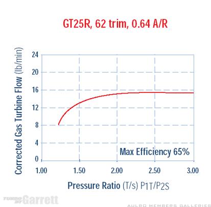
    The GT2052 turbine map shows that the turbine requires about 10.5 lb/min of exhaust flow at 1.84 PR, and about 11.2 lb/min at 2.98 PR. Exhaust flow above these rates (~ 50 to 60% in these 2 cases) should be diverted through the waste gate.


  3. #23
    Join Date
    Jul 2008
    Location
    Cessnock NSW
    Posts
    1,506
    Total Downloaded
    0
    Quote Originally Posted by Dougal View Post
    Tis the plan. My own noise requirements are far lower than and legal ones. Legally they just need a muffler present and an intact system which exits the rear.
    I'll get some practise with the work car, I figure a 2.5" on that 2.2 turbo 4cyl will be good enough practice for a 3" on a 3.9 turbo 4.
    Yeah that would be the go...this work car must cop some by the sound of it good test guinea pig

  4. #24
    Join Date
    Sep 2007
    Location
    Kiwiland
    Posts
    7,246
    Total Downloaded
    0
    Where did you get a copy of that text John? I've been looking for years. I bought a copy of Baines book instead as apparently a close second choice.

  5. #25
    Join Date
    Jul 2008
    Location
    Cessnock NSW
    Posts
    1,506
    Total Downloaded
    0
    Thanks John for that info its a good explanation..
    The example given for the gt2052 is a good indication of the problems associated with small turbos

    I should have done some real world testing of small turbos compared to the larger version before I stuffed the little one however it was sacrificial as it was only a test to see how far one can be pushed before failure...(gt2052 over 30psi sustained) longevity was another concern...IMO on a 4bd1t I would never put a turbo on with an exhaust AR smaller than .56 but that's only because I require more than normal boost figures mixed with the reasons you just posted...

  6. #26
    Join Date
    Jan 1970
    Location
    'The Creek' Captain Creek, QLD
    Posts
    3,724
    Total Downloaded
    0
    Quote Originally Posted by Dougal View Post
    Where did you get a copy of that text John? I've been looking for years. I bought a copy of Baines book instead as apparently a close second choice.
    Inter Library loan.

  7. #27
    Join Date
    Sep 2008
    Location
    Geelong, VIC
    Posts
    4,442
    Total Downloaded
    0
    FWIW - I took it for a quick run tonight to record some boost onset figures. Unfortunately its a lot cooler tonight (14degC) than the after run in my original post so the 2 lots of data don't fit together. Figured I post it up anyway.

    Boost (PSI) ==> RPM
    5==> 1500
    10==> 2000
    12==> 2200
    15==> 2500

    Although I didn't take note of the boost/RPM with the old 2.5" pipe, my recollection is that 5psi would have been about the same 1500 RPM, but I wasn't getting over 10psi until around 2500 RPM.

    I've also tracked down these graphs which match the specs of my turbo pretty closely.


    I thought I had my head around Bush65's good explanation of the GT2052 maps earlier so was trying to apply it to my T25G.
    The 2200rpm/20psi(PR 2.4 mass flow of about 18.9 lb/min) example is near the top of the map for my compressor.
    The 2600/25psi (PR 2.7 mass flow of about 24.7 lb/min) is miles outside it. I take that to mean that mine won't do 25psi.

    How do I work out the mass flow at 20psi for eg 2500 and 3200 RPM so I can plot them on the map?
    1985 County - Isuzu 4bd1 with HX30W turbo, LT95, 255/85-16 KM2's
    1988 120 with rust and potential
    1999 300tdi 130 single cab - "stock as bro"
    2003 D2a Td5 - the boss's daily drive

  8. #28
    Join Date
    Jan 1970
    Location
    'The Creek' Captain Creek, QLD
    Posts
    3,724
    Total Downloaded
    0
    Steve, I don't have time now, so will post it tomorrow.

    I've created a spreadsheet, which is a work in progress - I'm having trouble finding the reference temperatures and pressures that turbo manufacturers like Garrett use for corrected mass flow for their turbine maps. I have re-hashed the sheet for single turbos and need to make the sheet for compound turbos similar. When this is done I will be happy to share it.

  9. #29
    Join Date
    Sep 2007
    Location
    Kiwiland
    Posts
    7,246
    Total Downloaded
    0
    Here is one I prepared earlier.


  10. #30
    Join Date
    Sep 2008
    Location
    Geelong, VIC
    Posts
    4,442
    Total Downloaded
    0
    Thanks Dougal.
    So its as simple as plotting the same red line on the graph for my compressor?
    Also, are the red dots the full throttle points for particular RPM or am I on the wrong tram

    Steve
    1985 County - Isuzu 4bd1 with HX30W turbo, LT95, 255/85-16 KM2's
    1988 120 with rust and potential
    1999 300tdi 130 single cab - "stock as bro"
    2003 D2a Td5 - the boss's daily drive

Page 3 of 4 FirstFirst 1234 LastLast

Bookmarks

Bookmarks

Posting Permissions

  • You may not post new threads
  • You may not post replies
  • You may not post attachments
  • You may not edit your posts
  •  
Search AULRO.com ONLY!
Search All the Web!