See pages 336, 337 & 338 in Turbocharging the Internal Combustion Engine by Watson and Janota. The parts of Section 9.5 on these pages are worth reading for their relevance to this thread.
Note in Figure 9.21, the effect of exhaust system back pressure on Turbine inlet temperature (EGT or exhaust gas temperature) and Specific Fuel Consumption. The EGT results are self explanatory, SFC is how much fuel the engine requires to produce a unit of power per hour. Lower SFC means lower fuel consumption or more power from the same fuel.
Unfortunately the egt results given in the original post are affected by different ambient conditions when they were recorded. If the ambient conditions were the same, the lower egt would be consistent with the results for lower exhaust back pressure shown in Figure 9.21.
With the rise in use of jet turbines, etc. after WW2, the knowledge and development of turbo machinery was extensive. Much of the knowledge is applicable to turbochargers.
The power/torque required by the compressor must be supplied by the turbine and is a function of the turbine plus mechanical efficiency, the mass flow of the exhaust gas, the gas temperature at the turbine inlet, and the pressure ratio (or if you like the expansion ratio) across the turbine (i.e. TIP / TOP).
For example, if the required pressure/expansion ratio is 2.5 and the TOP, equal to the exhaust back pressure is 2 psig or approximately 16.7 psia at sea level, the required TIP is 2.5 x 16.7 = 41.75 psia ~ 27 psig. If the back pressure is reduced to 0.5 psig ~ 15.2 psia, the required TIP would be 2.5 x 15.2 = 38 psia ~ 23.3 psig. During the engine exhaust stroke a considerable amount of power is lost due to the piston acting against the pressure in the exhaust manifold (TIP). Another side effect of the higher TIP is an increase of the mass of residual exhaust gas in the cylinder during the inlet stroke.
So it is beneficial to reduce the TIP – this is reflected by the curve for SFC vs exhaust back pressure in Figure 9.21. BTW 0.05 bar ~ 0.73 psi and 0.2 bar ~ 2.9 psi.
Exhaust back pressure increases with gas velocity and reduction in diameter. As pipe diameter is increased the back pressure reduces, but above some point the returns diminish rapidly and further increase of diameter is of little worth for the engine speed used during normal driving.
Referring to Figure 9.22 on page 338, the recommended upper limit for exhaust back pressure is 0.05 bar (0.73 psi).
IMHO 3" would be worthwhile for a turbocharged 4BD1. If it was simple (it is not IMO) I would go bigger for my own compound turbo 4BD1T.
To realise the benefits of a free flowing exhaust system discussed here, the turbo and waste gate setting need to be matched to the engine. The waste gate is the appropriate device to use for regulating turbo speed and inlet pressure, not a restrictive exhaust system as some might be inferring.
Too many use a small turbo that produces boost at low engine rpm, then create excessive TIP by tightening the waste gate in an attempt to get boost pressure that is off the compressor map without knowing what is going on. A turbo from a TD5 at 25+ psi on a fueled-up 4BD1 for a classic example.
For an inter-cooled 4BD1 at 2200 rpm, 20 psig boost pressure (PR 2.4), and 0.7 compressor efficiency, the compressor will require approximately 25 HP to produce the mass flow of about 18.9 lb/min. The exhaust velocity will be approximately 242 ft/min in a 3” pipe or 348 ft/min in a 2.5” pipe. To produce the power required by the compressor the PR for the turbine will be about 1.84 at an egt of 650C.
At 2600 rpm, 25 psi boost (PR 2.7), and 0.7 compressor efficiency, the compressor will require approximately 38 HP to produce the mass flow of about 24.7 lb/min. Exhaust velocity will be approximately 290 ft/min in a 3” pipe or 417 ft/min in a 2.5” pipe. The required PR for the turbine will be about 2.98 at an egt of 650C.
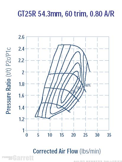
For a GT2052 turbo (the size used on a TD5), 18.9 lb/min at PR2.4 is almost off the compressor map, and 24.7 lb/min at PR 2.7 is well off the compressor map.
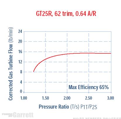
The GT2052 turbine map shows that the turbine requires about 10.5 lb/min of exhaust flow at 1.84 PR, and about 11.2 lb/min at 2.98 PR. Exhaust flow above these rates (~ 50 to 60% in these 2 cases) should be diverted through the waste gate.


 Reply With Quote


 good test guinea pig


Bookmarks