Are you referring to the map Dougal posted for his smaller compressor, or mine?
Here's the map for mine with a very rough plot of the full-load line from Dougals.
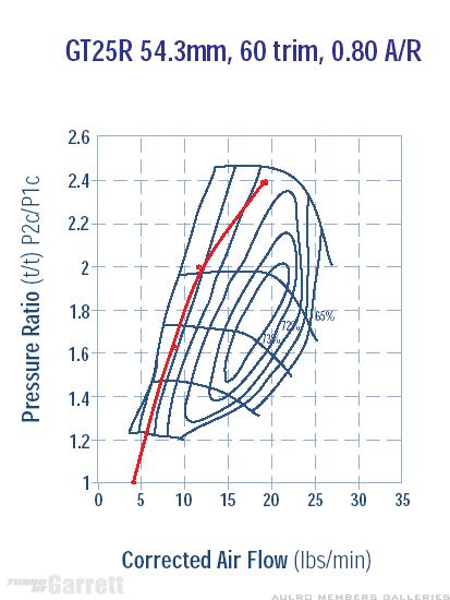
If I've understood correctly, then it should be pretty happy to ~20psi (as Dougal suggested earlier). Definitely not trying to get 25psi out of it!
I'm not sure I get what you mean about there being less energy in the exhaust now since the EGT has dropped. Temperature is only one component of the exhaust energy and since its essentially the same fuel going in I would have thought the exhaust would have the same energy.
The original purpose behind the larger exhaust was that I was sure it was choking on the 2.5" system. Others have reported getting sustained 15psi at reasonable EGT's, but I wasn't able to fuel it up enough to get that and stay below ~700degC under sustained load. I'm pretty much happy I've proved that was the case as I now have the same boost with much lower EGT.
I'm still not getting a solid 15psi, but now have the headroom in EGT to be able to fuel it to build the extra boost. Will be interesting to see how it behaves.
I'm very much a see it, touch it, learn it sort of person - so its great that there are people around here that are prepared to share their understanding of the theory and maths side of things and help me put all the pieces together in my head.
Steve


 Reply With Quote

Bookmarks