

 Reply With Quote
What is "Blue Box"?

 Wizard
I think the liquid steel is a KBS product? Haven't had much luck locating it here in Perth, (although I haven't looked that hard). I'll put these aside for spares, and to trial the method you've listed, (in the long term). I do have new non blue box ones to go on the car.Originally Posted by chazza

I've had to resort to blue box parts for a couple of pieces as there was nothing else available, but they're more cosmetic parts, other than rotating, sealing, or machined parts.
Cheers,
Master
What is "Blue Box"?
ChatterBox
SupporterThe dreaded Britpart....................... rightly or wrongly.
Cheers,
TopicToaster
I have to say that I'm enjoying this thread and to answer the question by Landyandy, mate you just have to make time LOL, I'm now sorta semi-retired I have a wife n 6 x 4 legged dependants, 7 bantams, and fish in ponds LOL, but you just have to swing it between all manner of things and a shed full of stuff 2 metal lathes a mill/drill and other stuff including this
and from another perspective
you just have to make time out of nothing LOL but I must admit I don't have any kids living at home well I'm almost 68 LOL cheers Dennis
ps TimNZ sorry for the slight off topic hi-jack,,.
Lord Jock
Yep! And "Blue Box" or should that be "Blue Bag" radiator hoses perish about six months after fitting. Mind you they sat in the shed for about six months before fitment!
Bloody annoying to say the least!!!
Cheers, Mick.
1974 S3 88 Holden 186.
1971 S2A 88
1971 S2A 109 6 cyl. tray back.
1964 S2A 88 "Starfire Four" engine!
1972 S3 88 x 2
1959 S2 88 ARN 111-014
1959 S2 88 ARN 111-556
1988 Perentie 110 FFR ARN 48-728 steering now KLR PAS!
REMLR 88
1969 BSA Bantam B175
Wizard
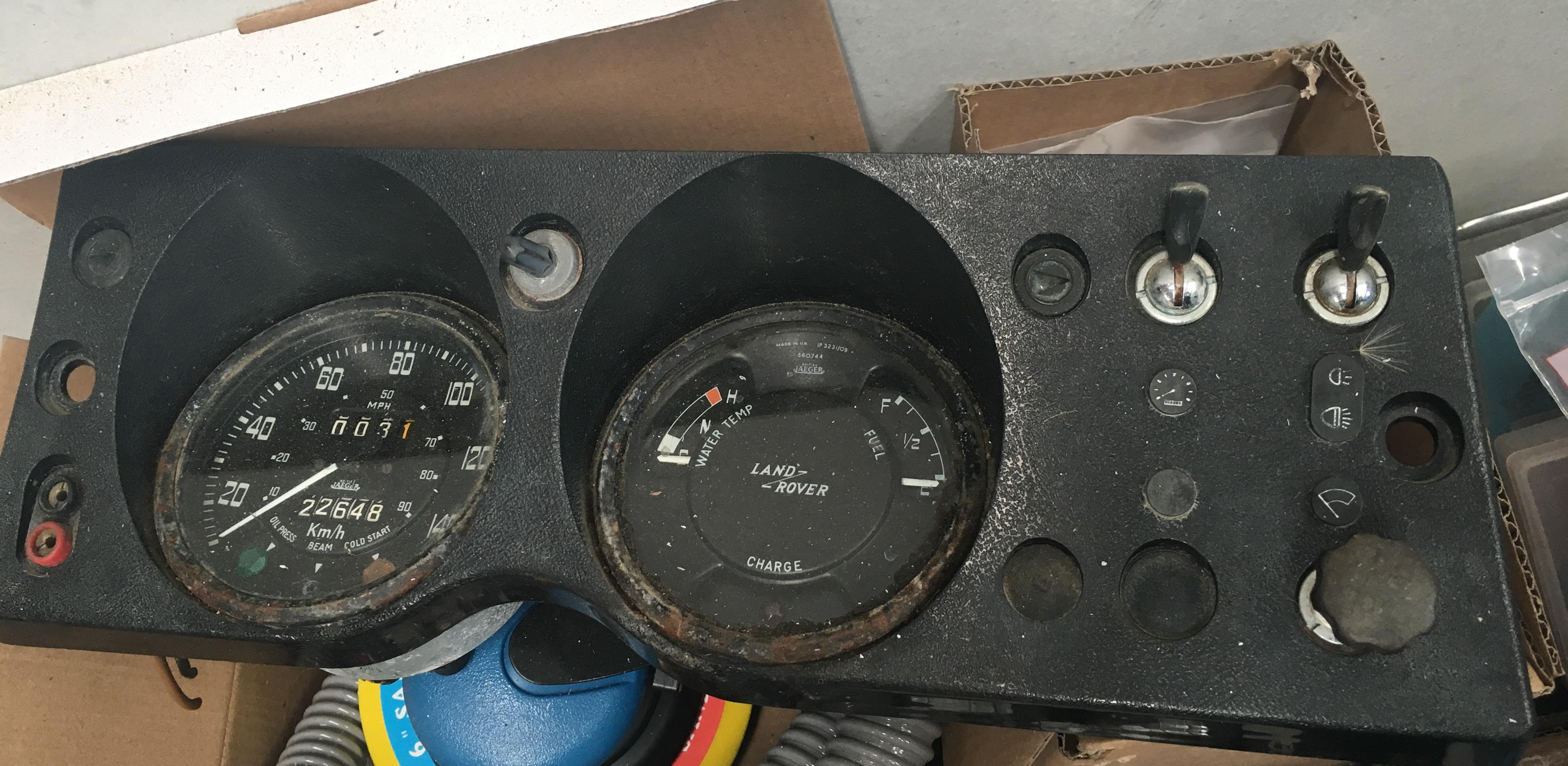
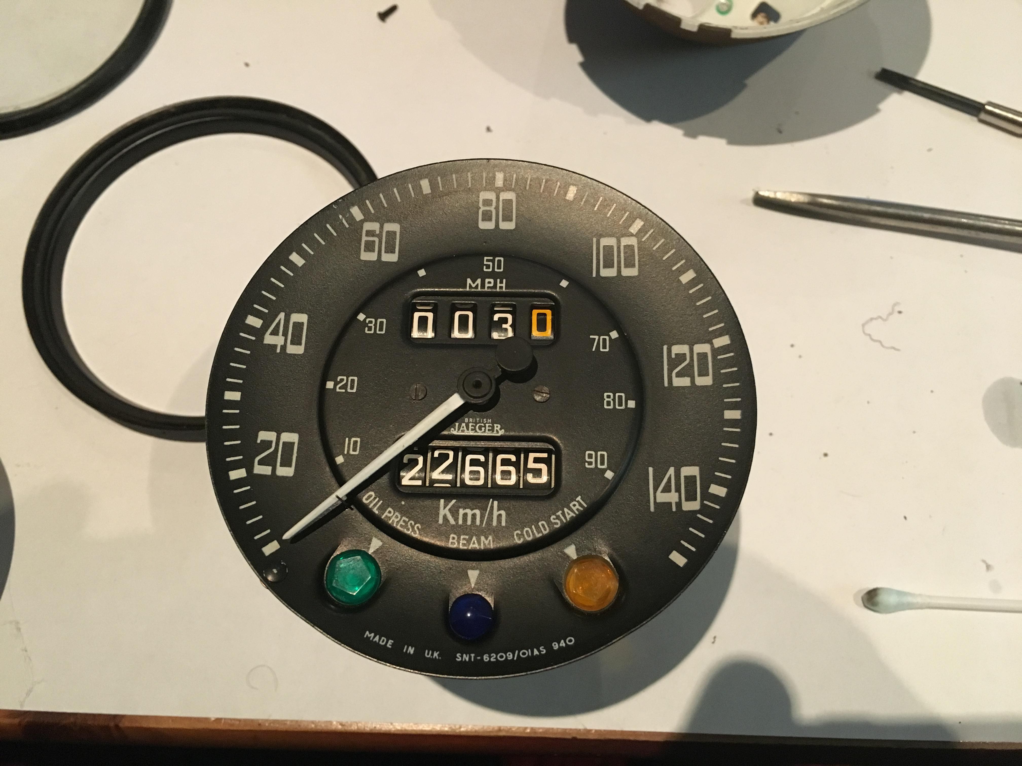
Got started on the binnacle whilst sat down in front of the idiot box tonight. Aside from generally schmoo around the clocks, the panel light switch is frozen solid, and the high beam lens of the speedo is broken off.
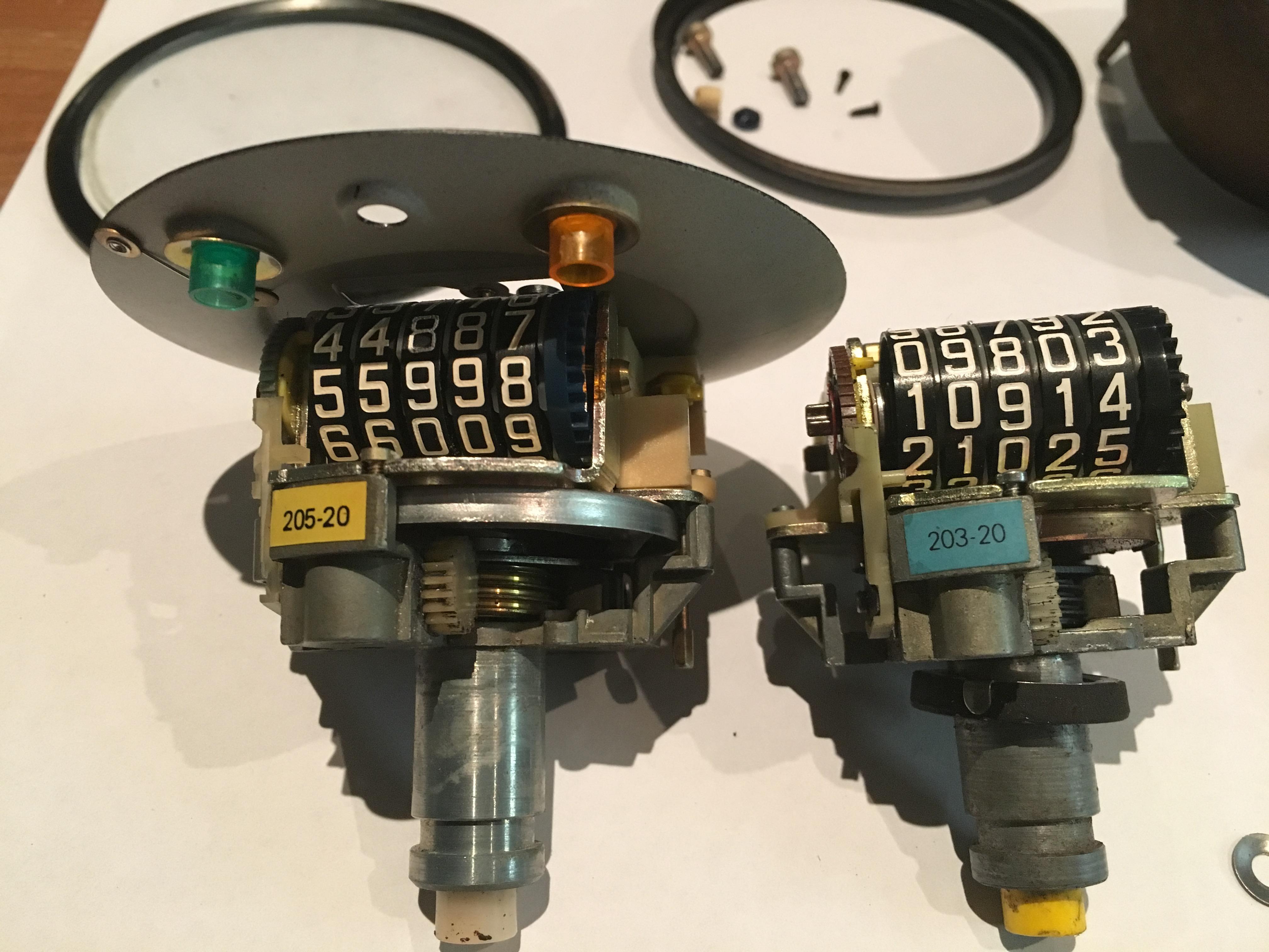
A spare speedo was aquired, I decided to rob the high beam lens of this and repair my original one as the spare had a different code on the sticker inside, (I assume it has a different ratio and is off a 109), and the clock face on the original is in slightly better nick.
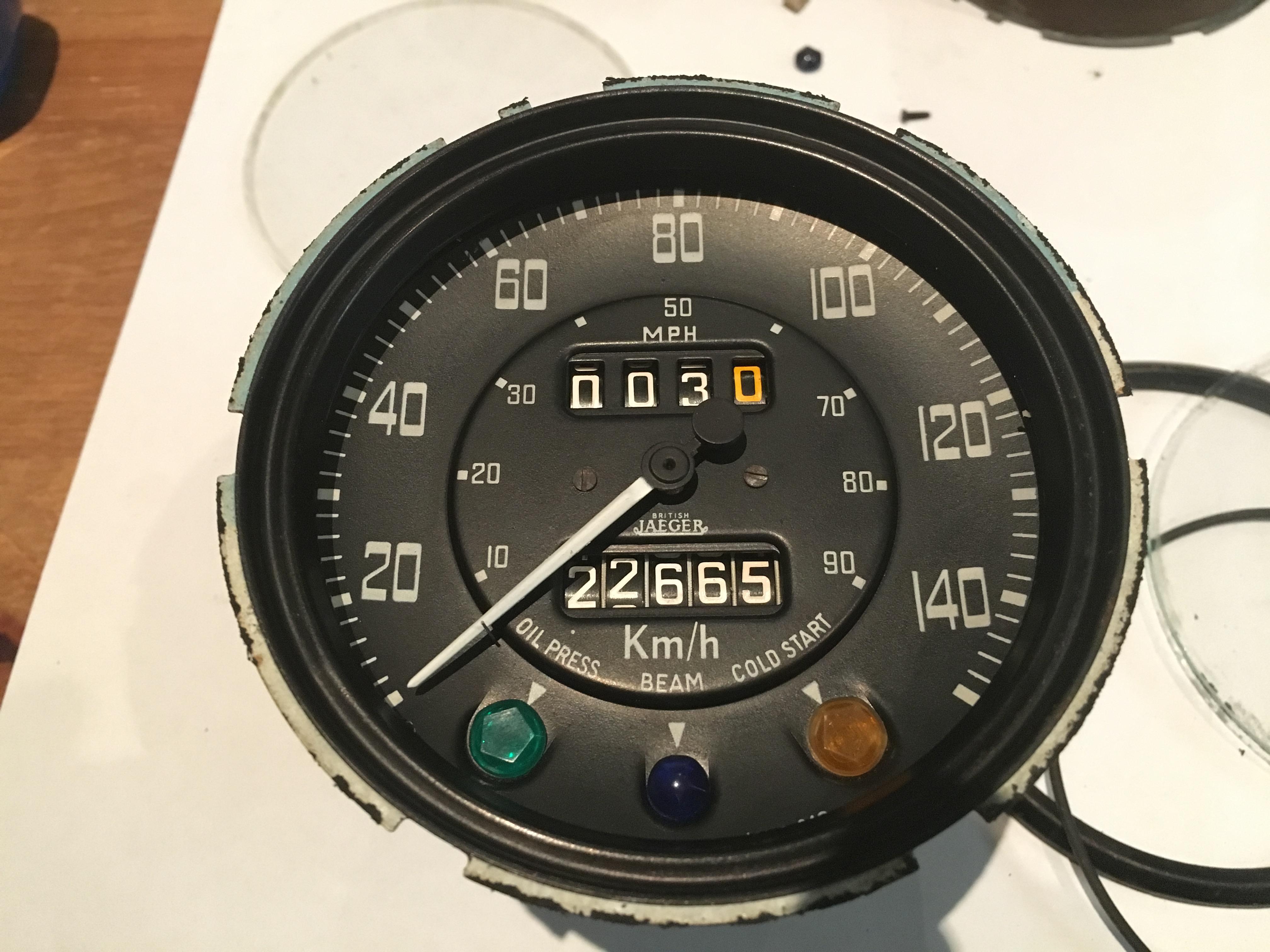
The bezel looks like it should rotate and then come off, (there are little tabs on the bezel that line up with cut outs on the housing), however I had to pry the tabs up to release it due to the corrosion/goo/sealant holding it on. I have replacement glass and bezels on the way which should be here soon.
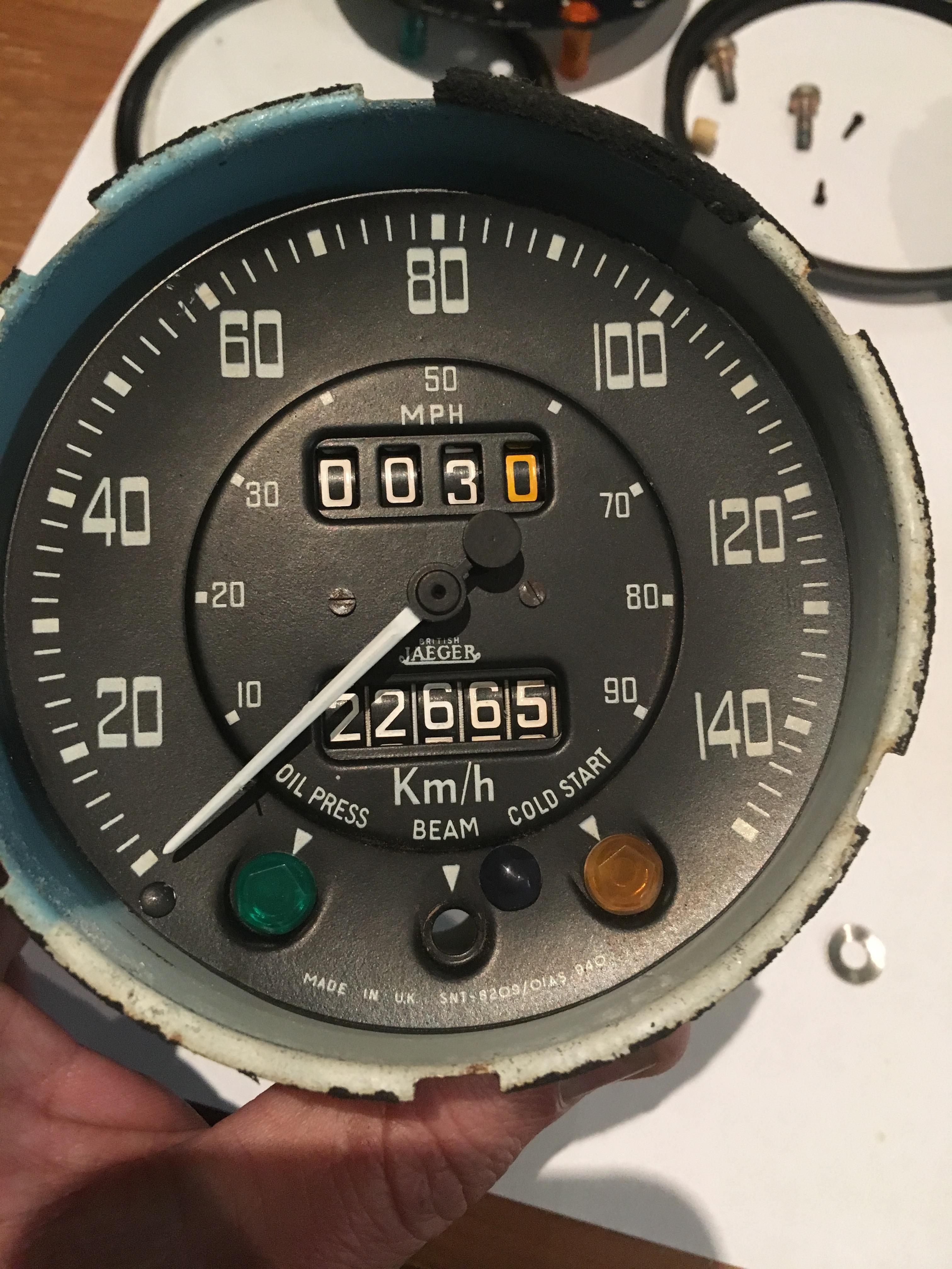
Original Jaeger gauge on the left, older, (I think), Smiths on the right. The "Smiths" name is blacked out for some reason.
The lenses are held in with a conical washer, which was carefully prised off.
Speedo with the replacement lens fitted, and clock face cleaned gently with some glass cleaner, cotton buds, and the micro fibre cloth stolen from my camera bag
Inner bezel also needed cleaning
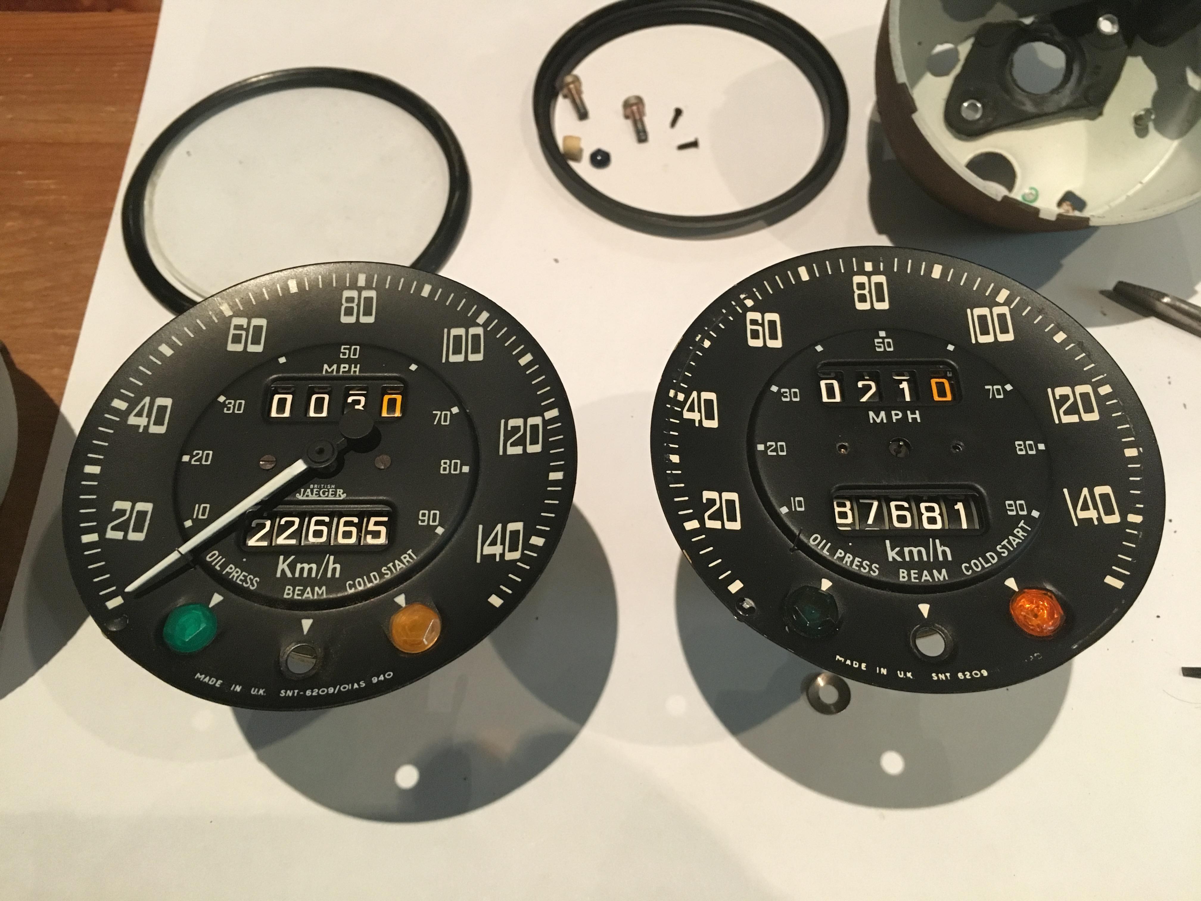
The Jaeger housing (left) has a light blue backing around the top, whilst the Smiths is completely white. I'm not sure what effect the blue is supposed to give? Maybe make the yellowish back light appear more white?
All back together, just need to wait for the new lens and bezel, oh and repeat this process on the other clock!
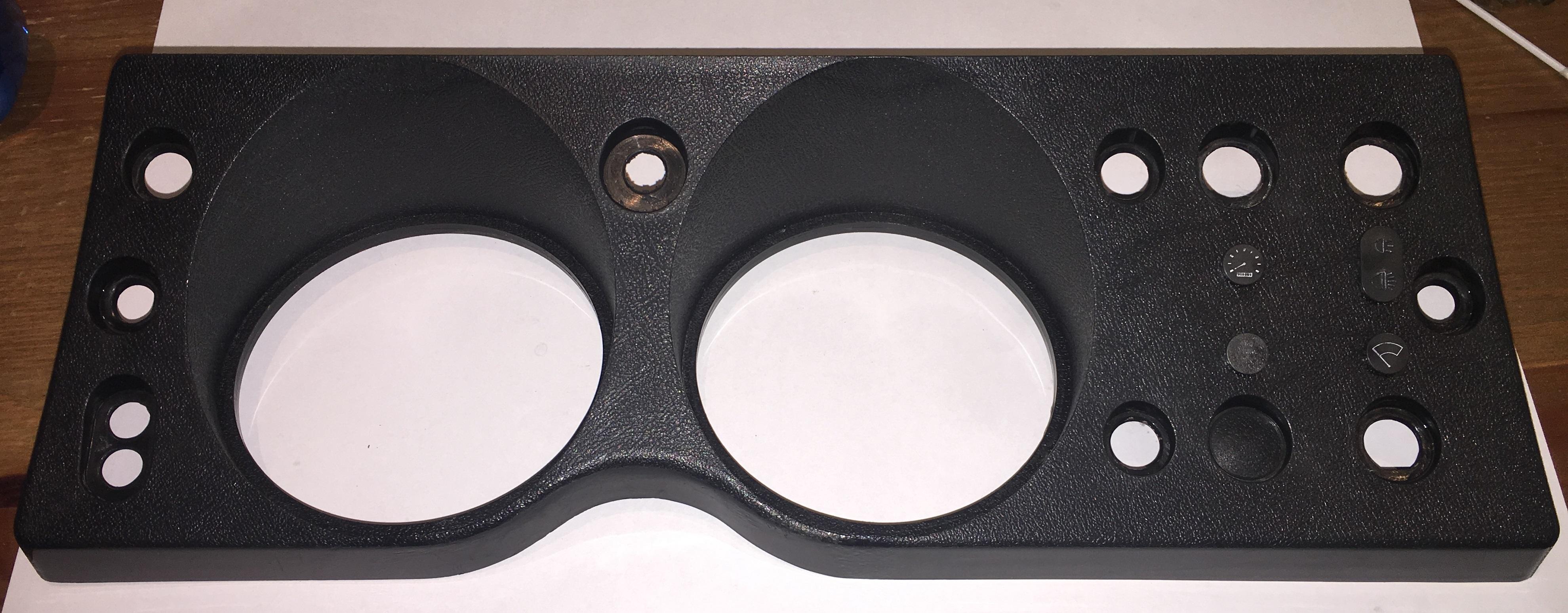
Gave the binnacle a good clean also. I used Meguiars interior cleaner, a soft brush, microfibre cloth, and plenty of warm water. Pretty happy with how it came up
Cheers,
ChatterBox
Nice work there Tim. I've got to do the instruments on mine too to clean out several years of Pilbara dust. I have given some plastic parts like your binnacle a quick coat with a satin black spray can and they come up great too.
RoverLord
THAT IS AWESOME Dennis.
Steam has always interested me.I love looking at old steam locos and farm machinery.That scale model is loverly.
ENJOY
Andrew
DISCOVERY IS TO BE DISOWNED
Midlife Crisis.Im going to get stuck into mine early and ENJOY it.
Snow White MY14 TDV6 D4
Alotta Fagina MY14 CAT 12M Motor Grader
2003 Stacer 525 Sea Master Sport
I made the 1 millionth AULRO post
Wizard
Went to pick the replacement outriggers today, but unfortunately they're not finishedThey should be done next week, but I won't get the chance to fit them till after Christmas.
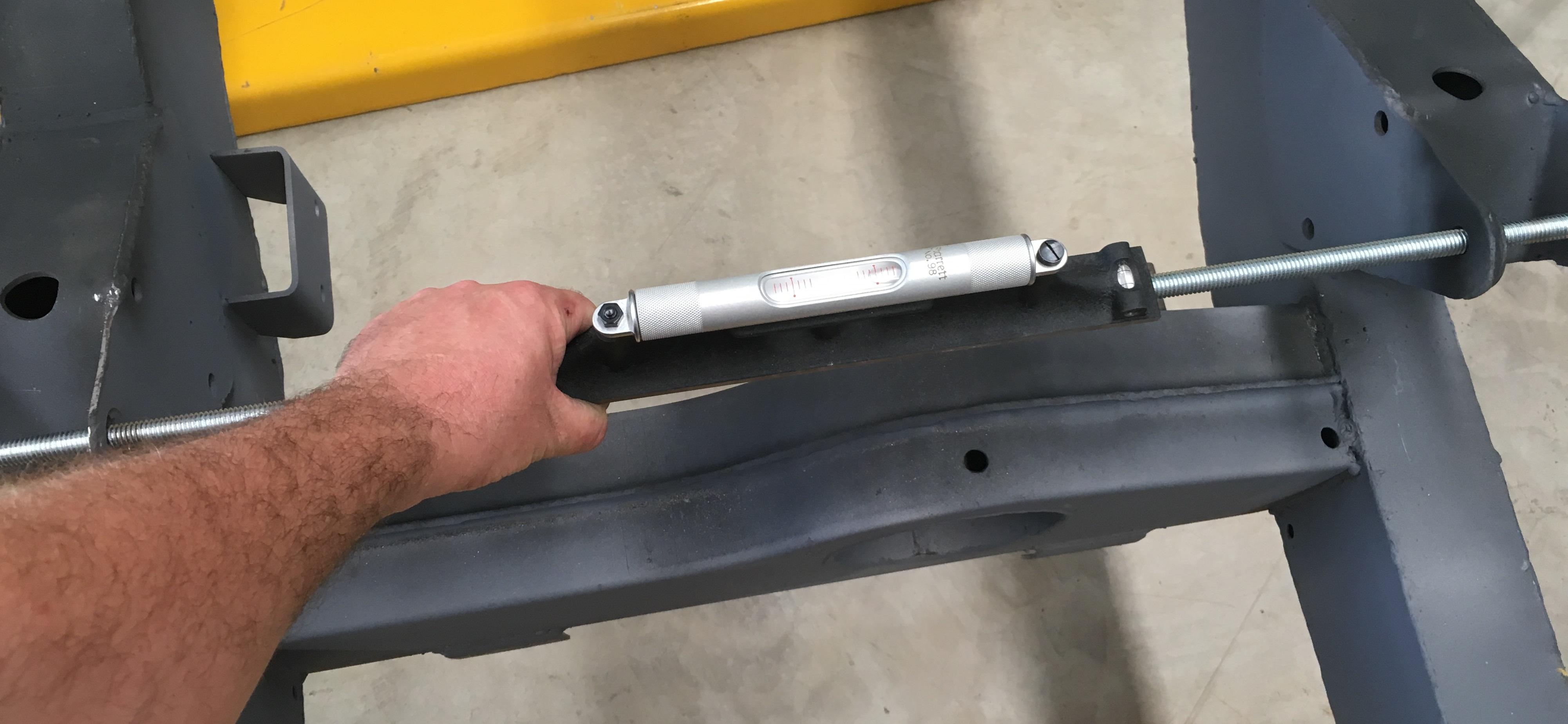
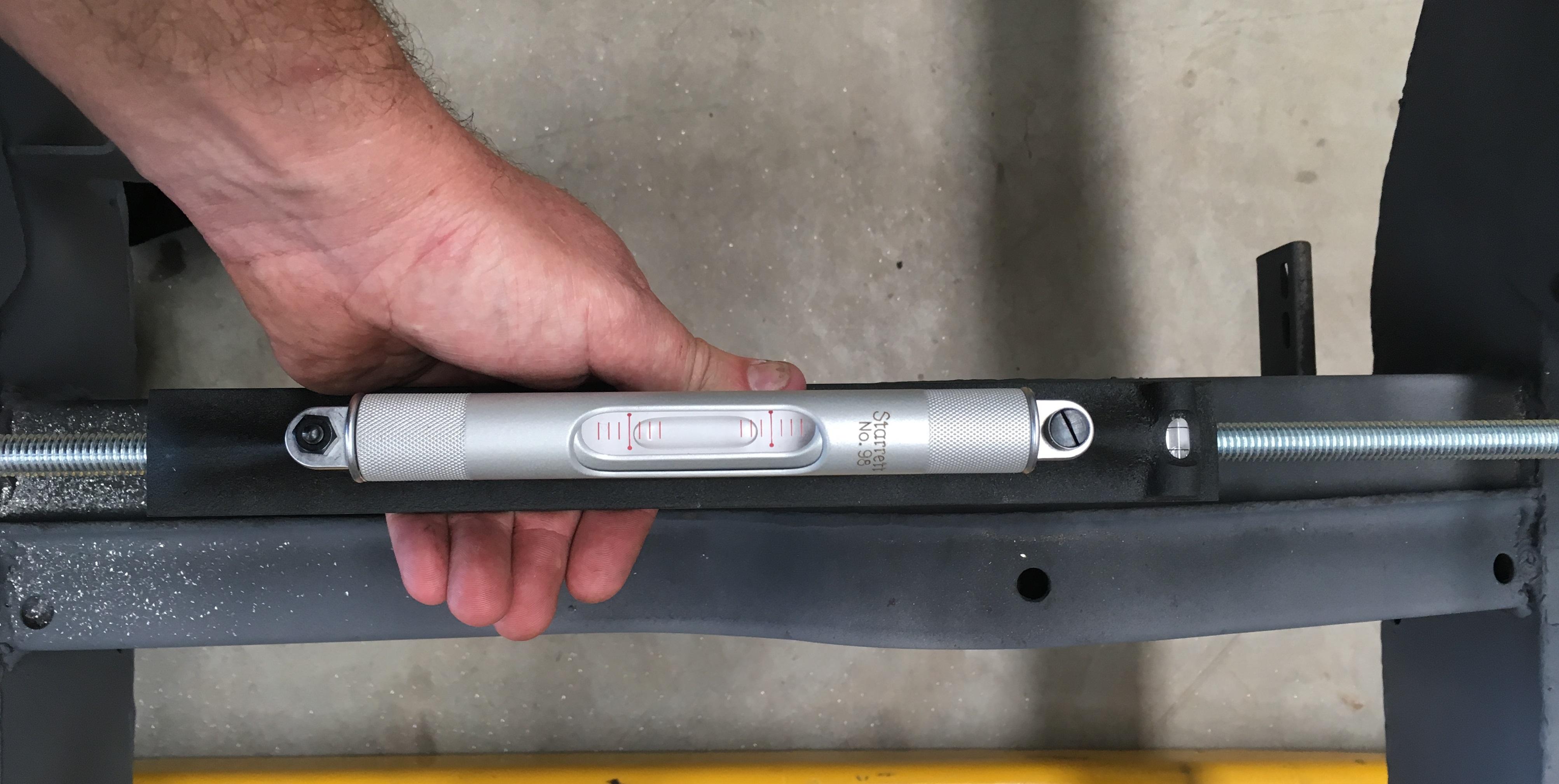
Anyway, got on to the last spring mount this evening. For as long as anyone can remember the Landy has had a list to starboard, and when I was trying to line up the threaded rod I think I've found out why. The distance from the spring bolt, (where the threaded rod is), is at least half an inch closer to the chassis on the drivers side.
I levelled the chassis as best I could, by checking the level at various points down the chassis, (it was actually pretty close at all the places I measured). It's a bit hard to see the bubble in the level in the picture, but it's all the way over to the right.
(Yes, I know I'm probably being a bit picky using a level thats graduations measure 0.42mm per meter, given that 70's BL used tolerances to the closest inch)
A short bit of surgery with the die grinder, and the level was much better:
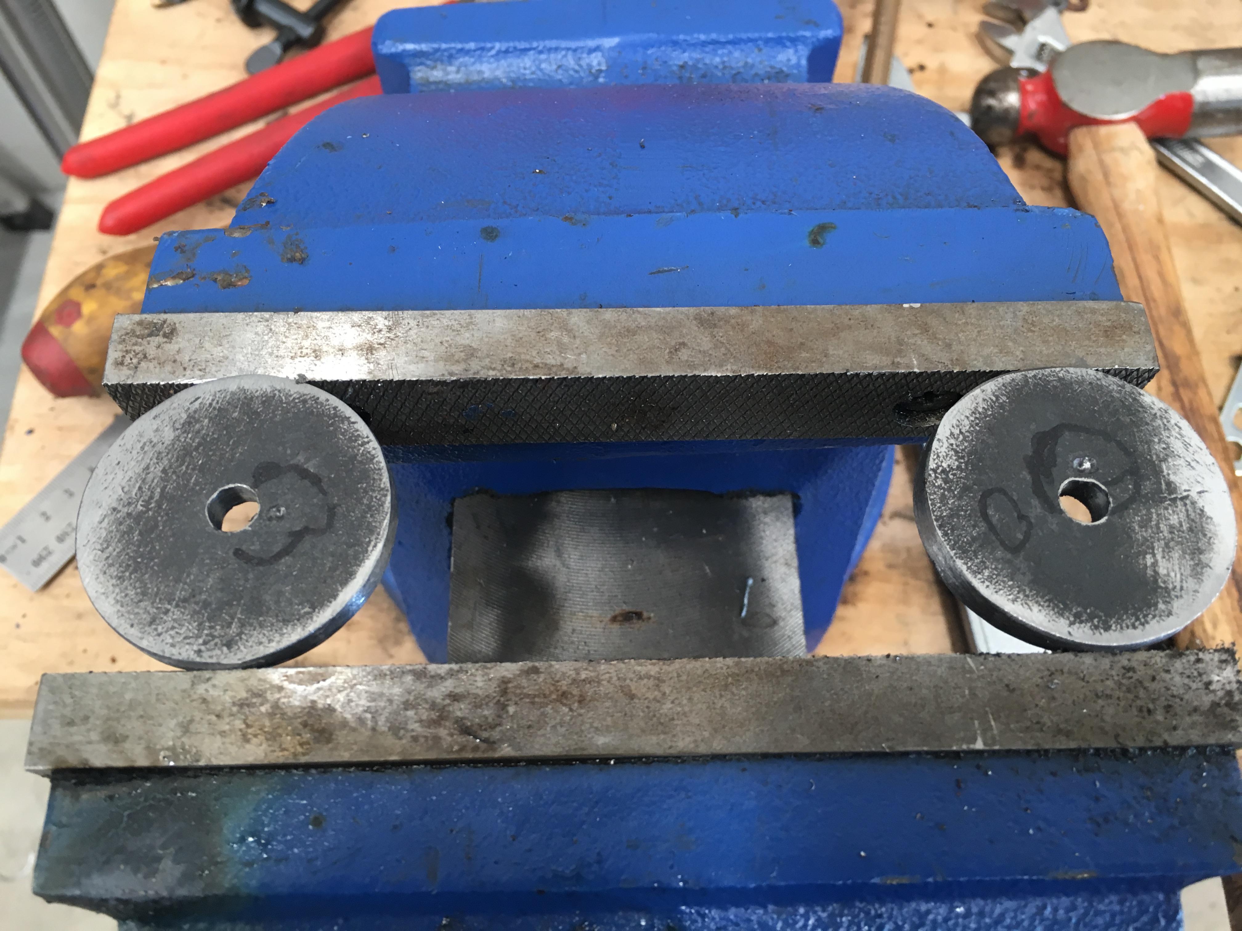
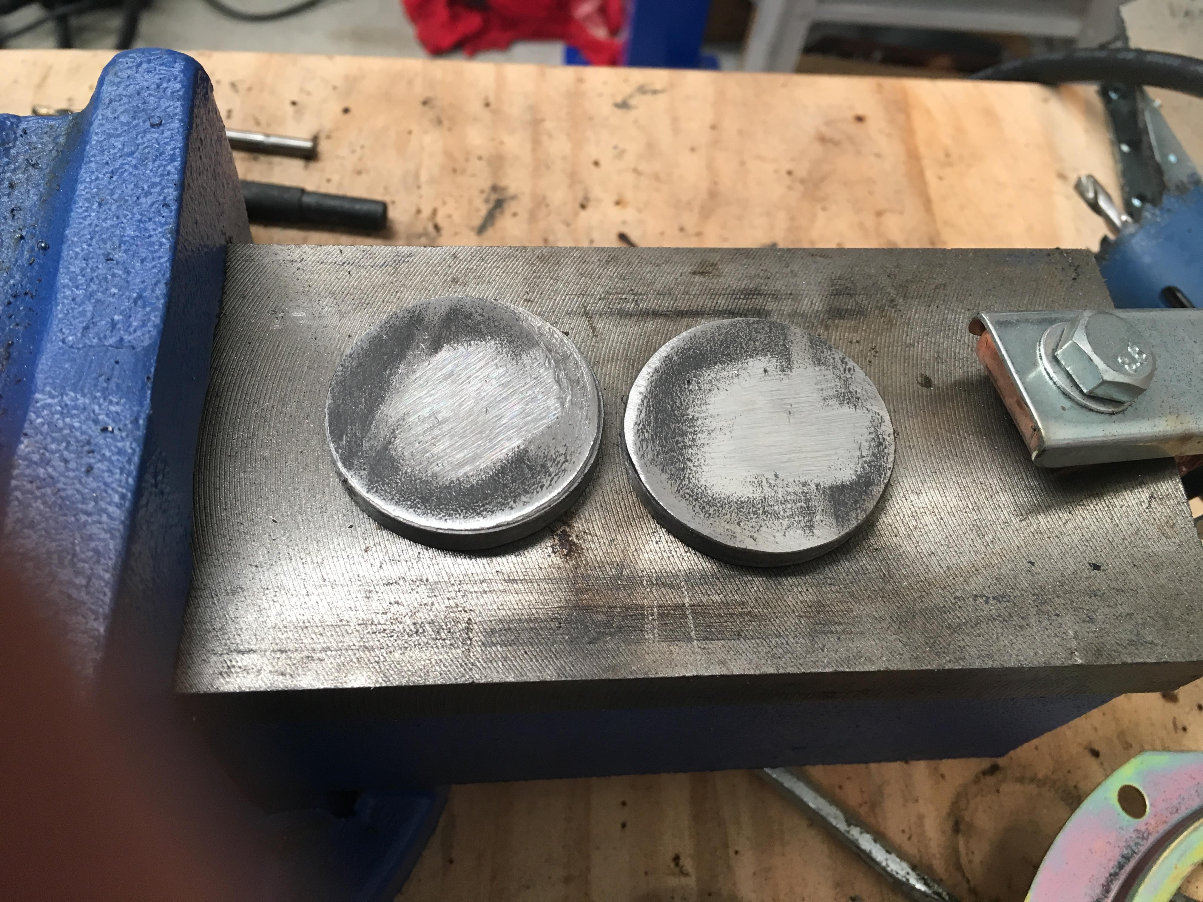
New "washers" were cut out of some 6mm plate:
But the holes needed to be moved off center, so the holes from the hole saw drill needed to be filled in first:
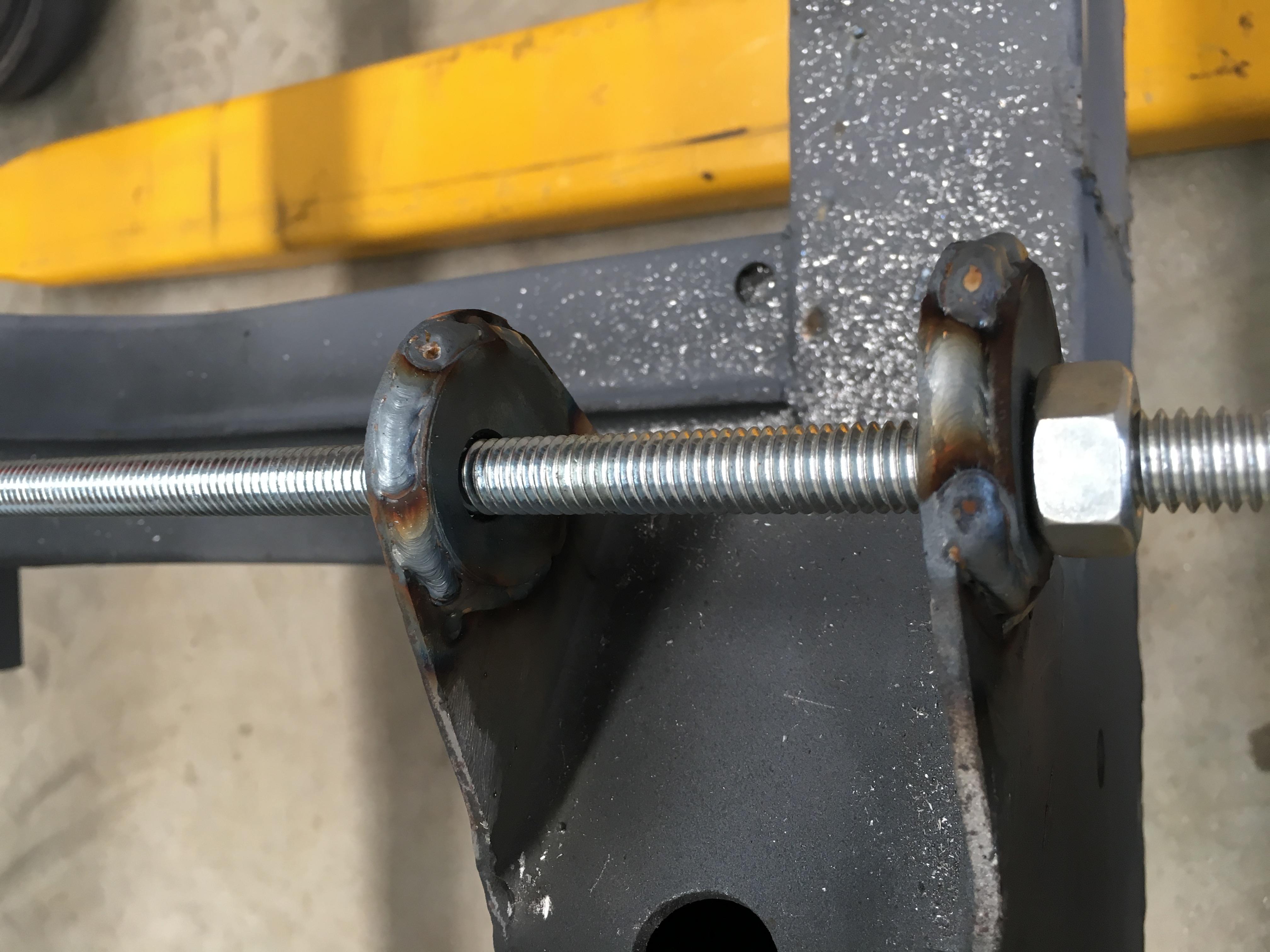
Then they could be redrilled and welded on. (The distance between the rear most mount and threaded rod was checked to be equal on both sides)
I still need to fill in the wear on the rest of the chassis mount, but that can wait till tomorrow.
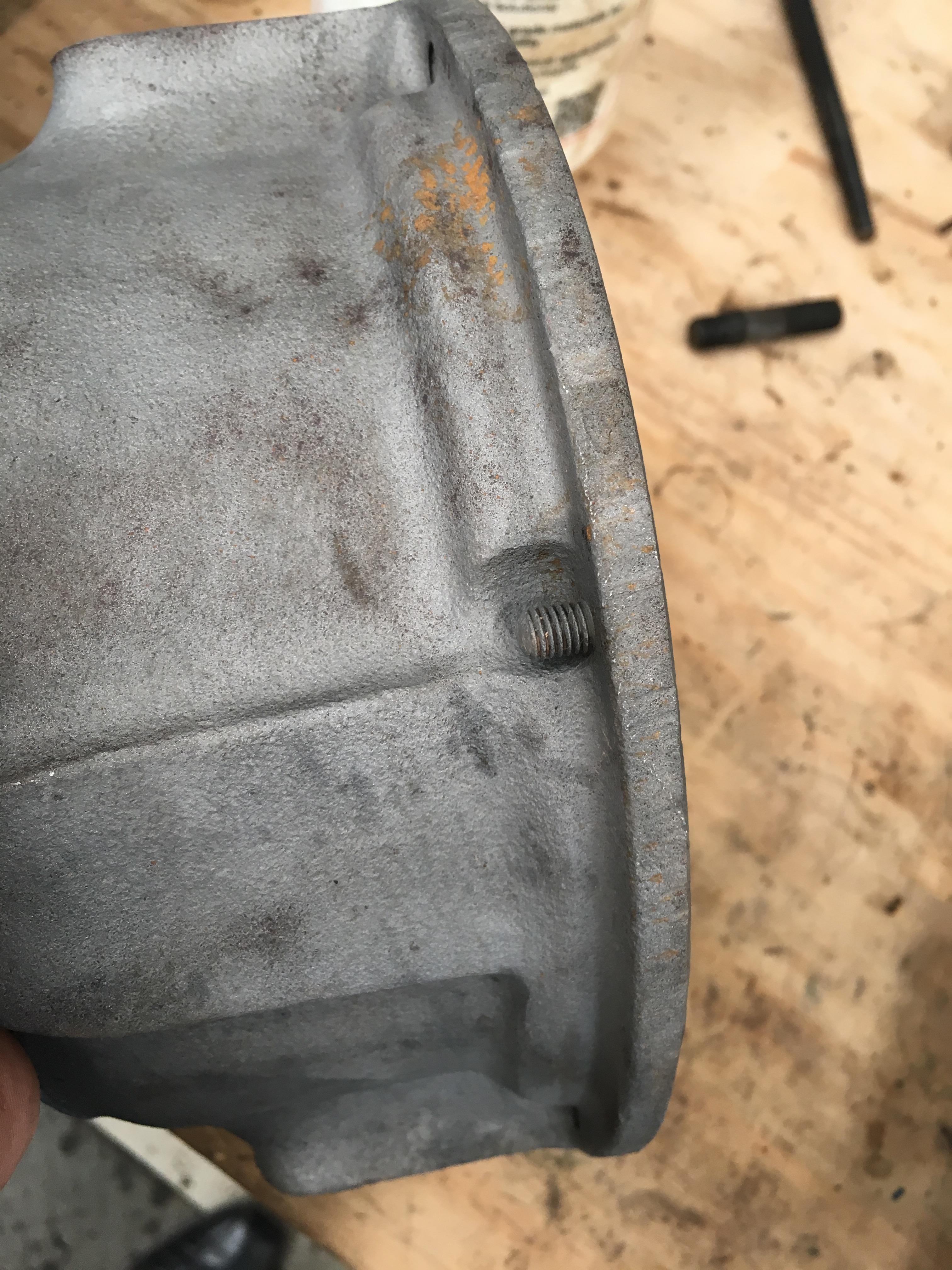
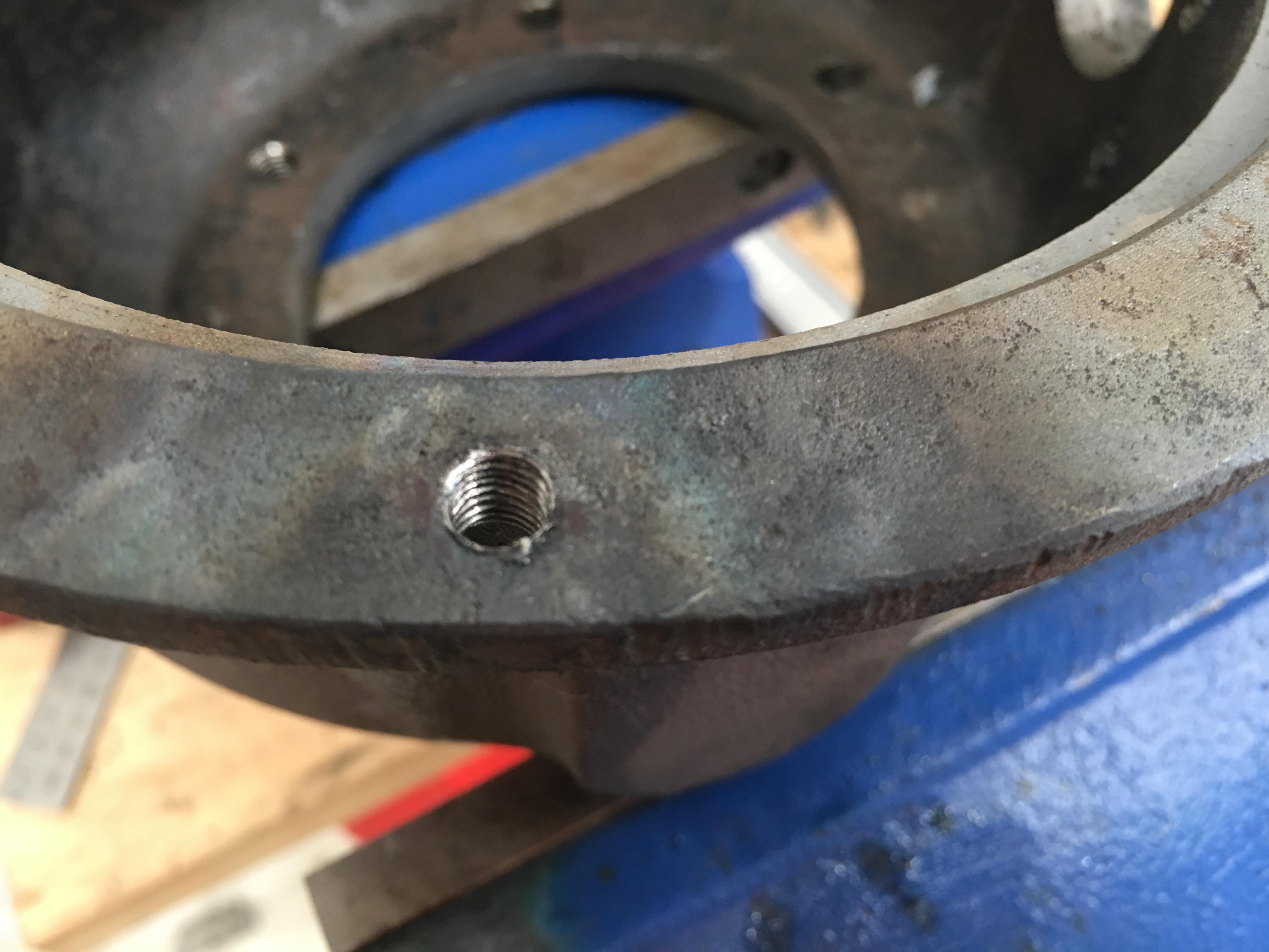
The other "5 minute job" I tackled was to remove this broken bolt in the outer swivel housing, easy right....
I tried drilling it first, turns out it's a BSF bolt (1/4"), and a high tensile one at that. I started with a 3mm cobalt drill bit, may as well used a piece of wooden dowel.
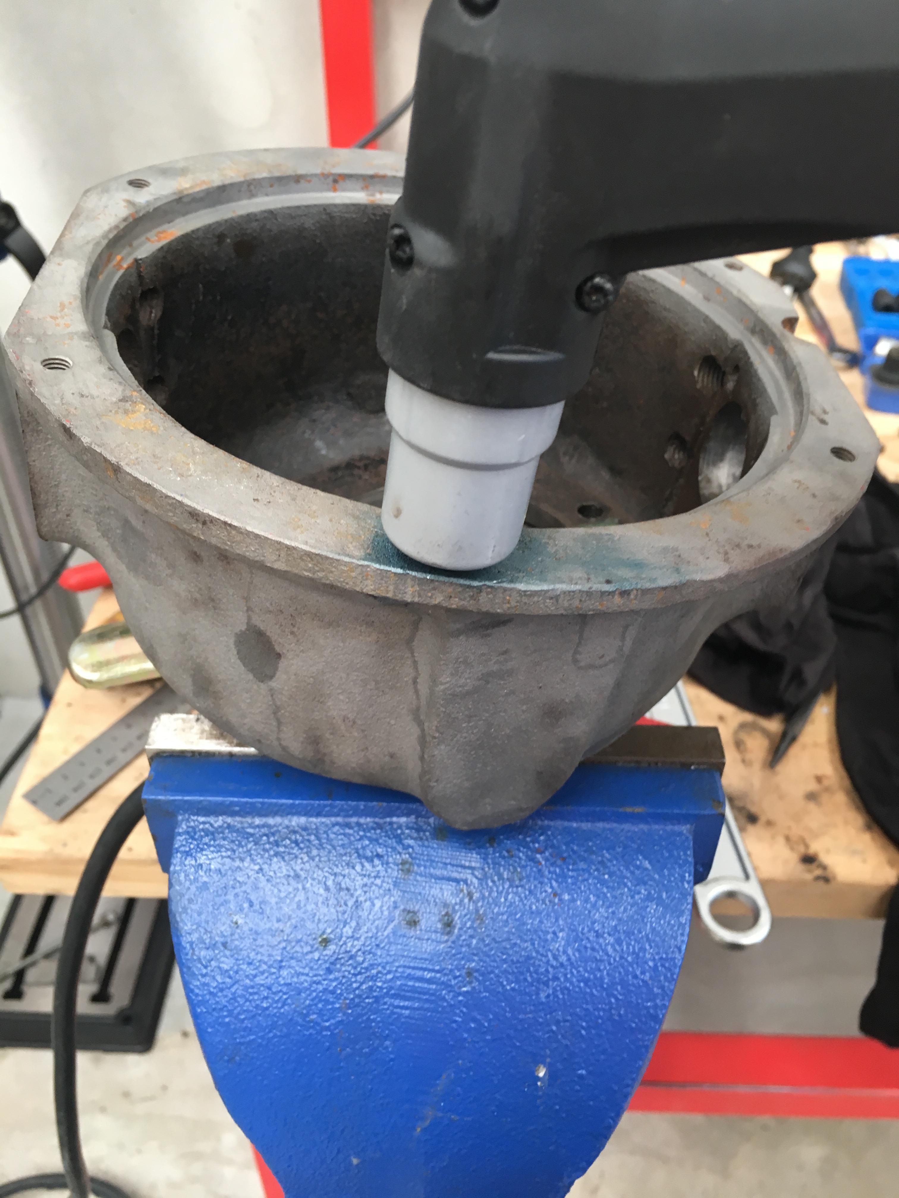
So.... plasma cutter?
Worked surprisingly well
The hole was then drilled out with a 5mm bit, which sacrificed it's life by doing so, given how hard the material was. I didn't fancy the little 1/4" BSF tap's chances of cutting away the rest of the high tensile bolt, so the gas torch was broken out, the remains of the bolt heated, then allowed to cool. This made it soft enough to tap out the hole:
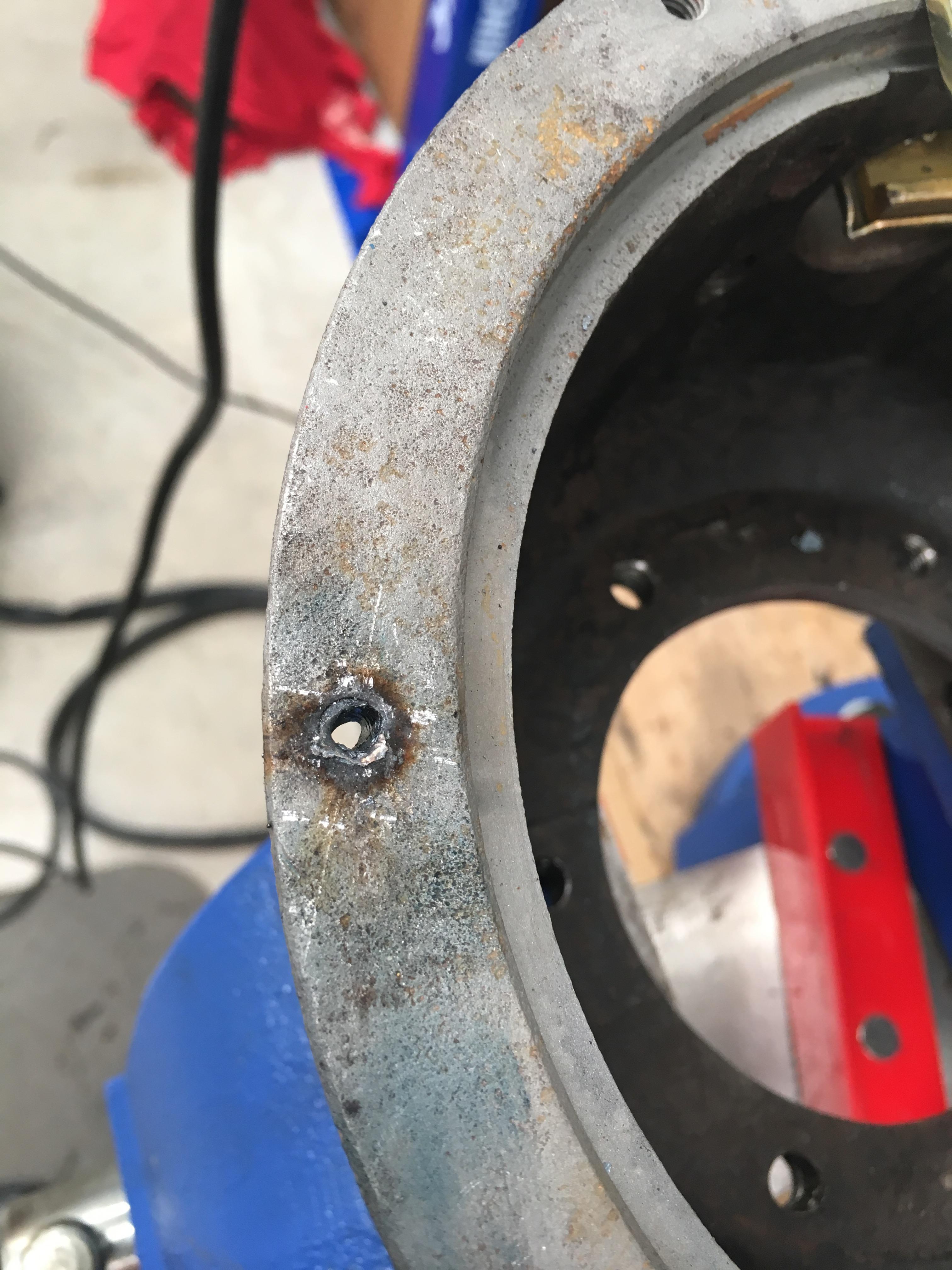
And... all done:
Cheers,
Wizard
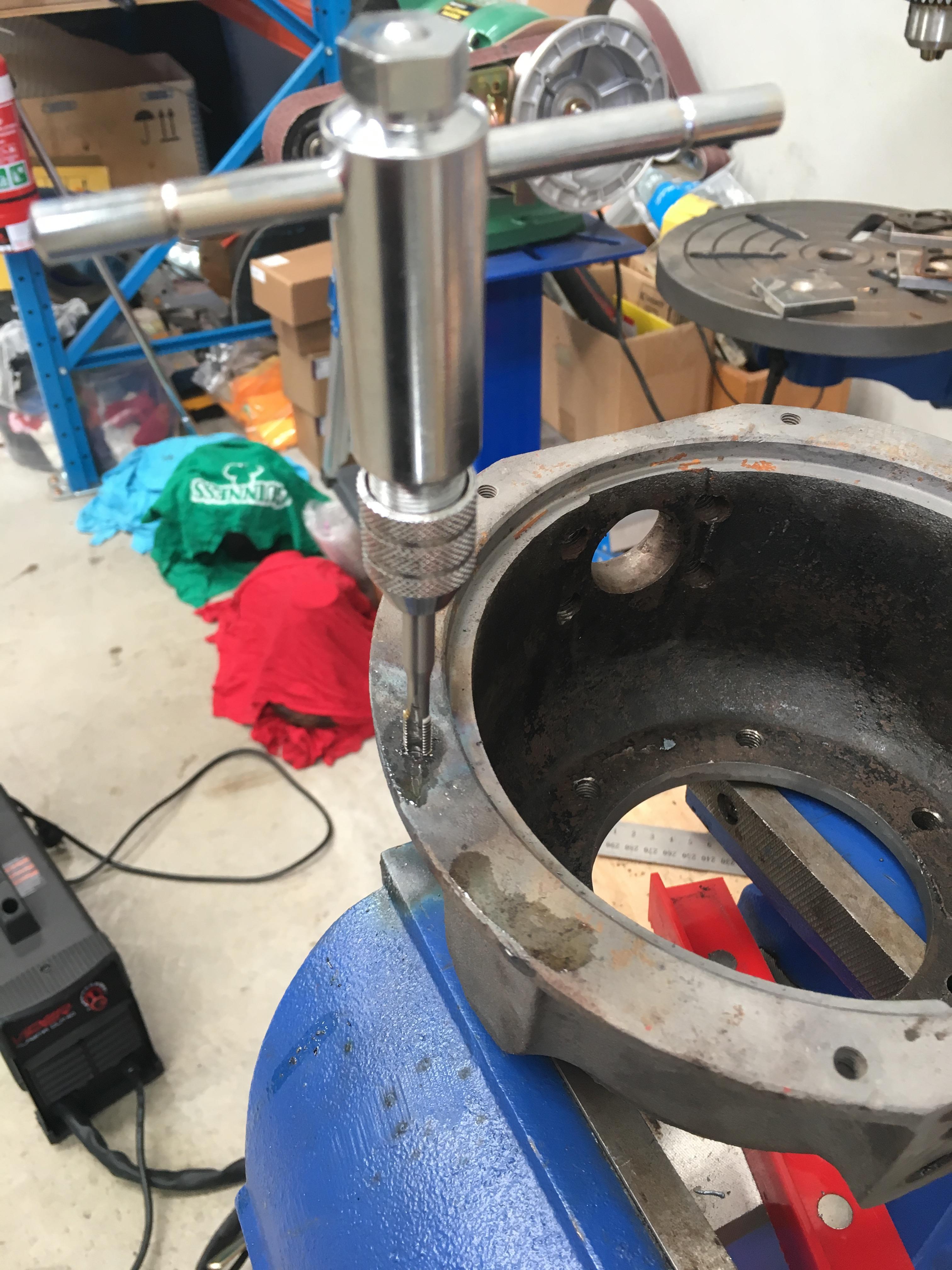
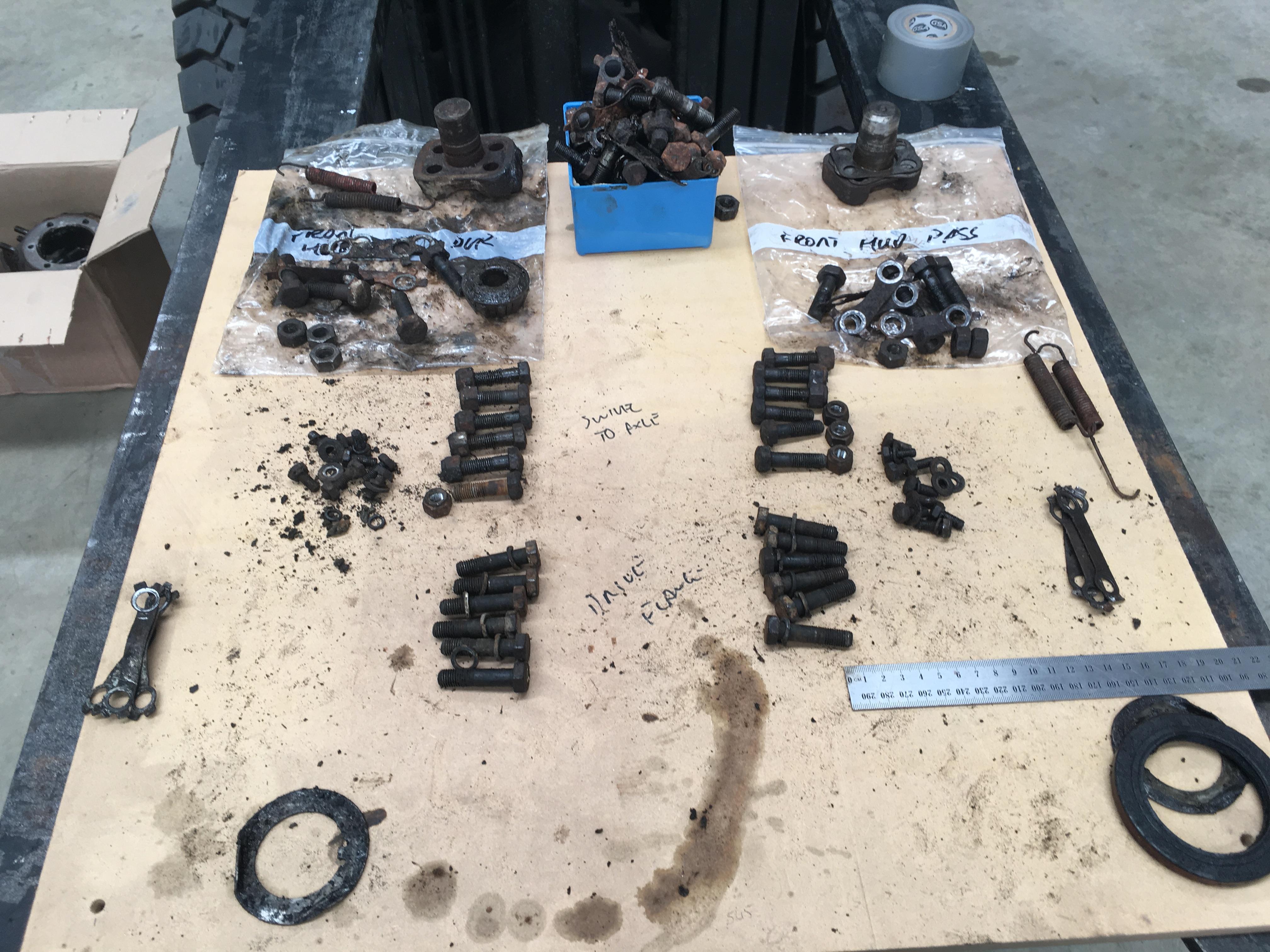
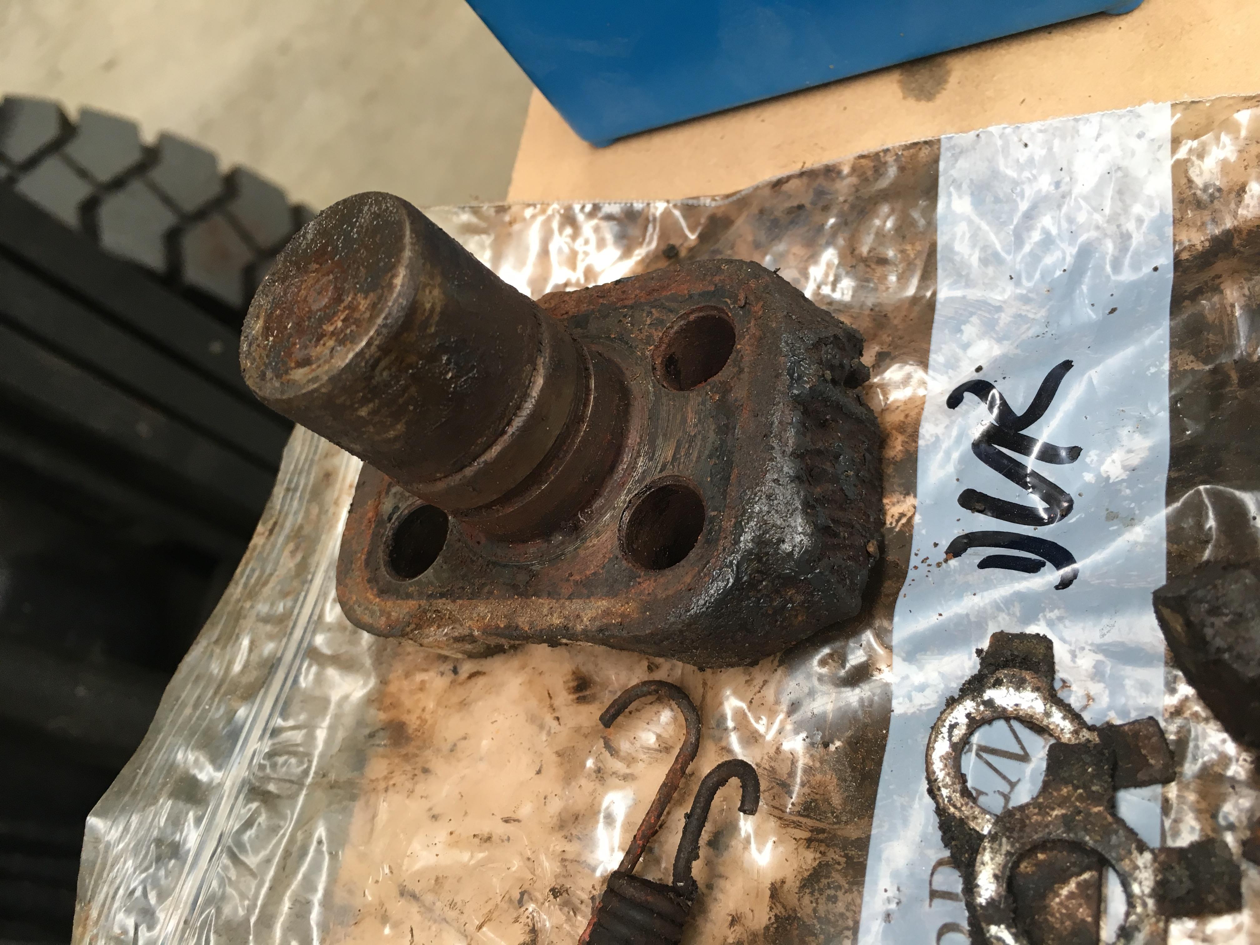
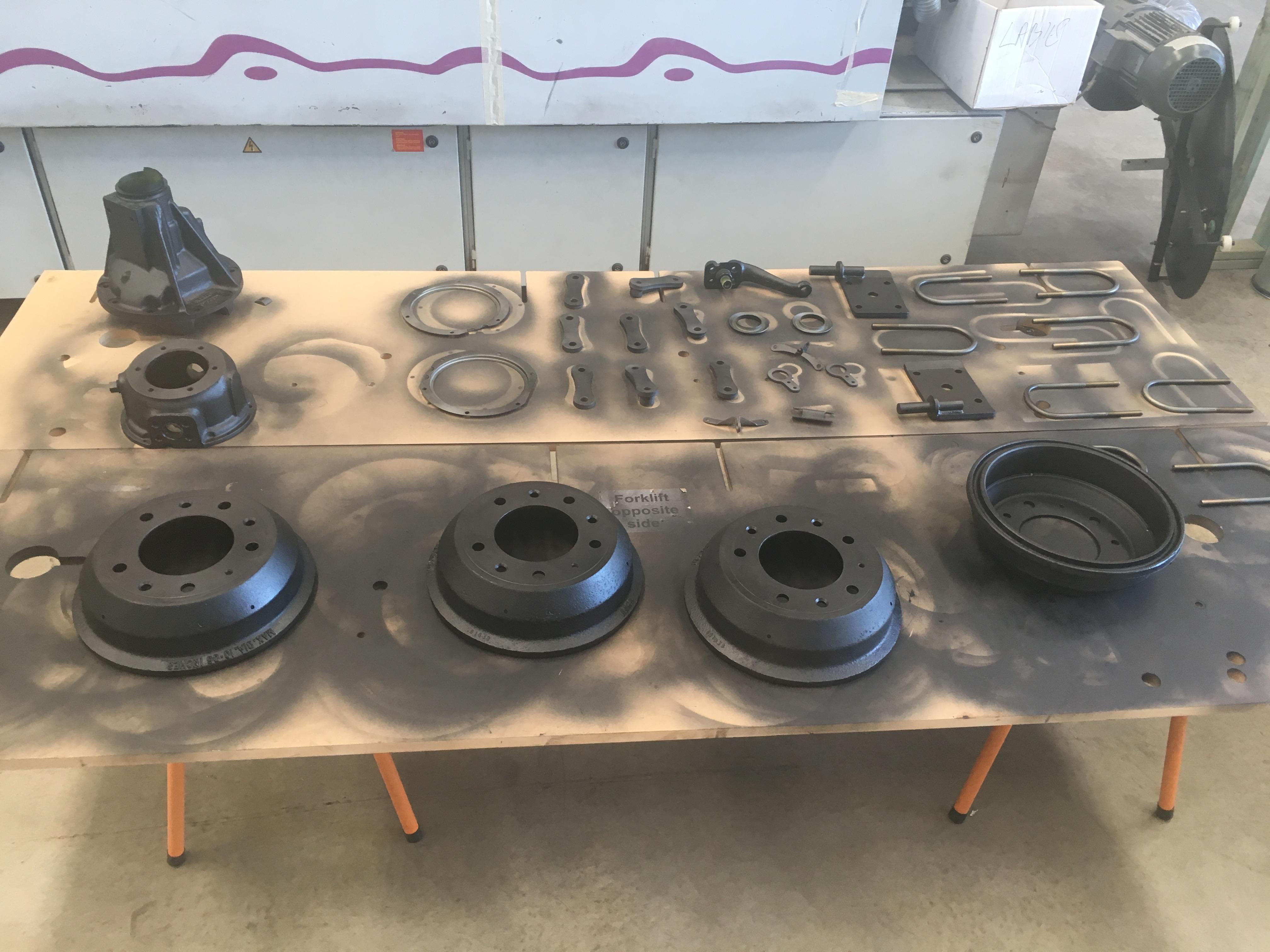
Started sorting through the nuts, bolts and other bits of the front axle today. Got all the bolts organised for which ones need cleaning, and any brackets that need blasting and painting set aside.
If in doubt, gas axe?
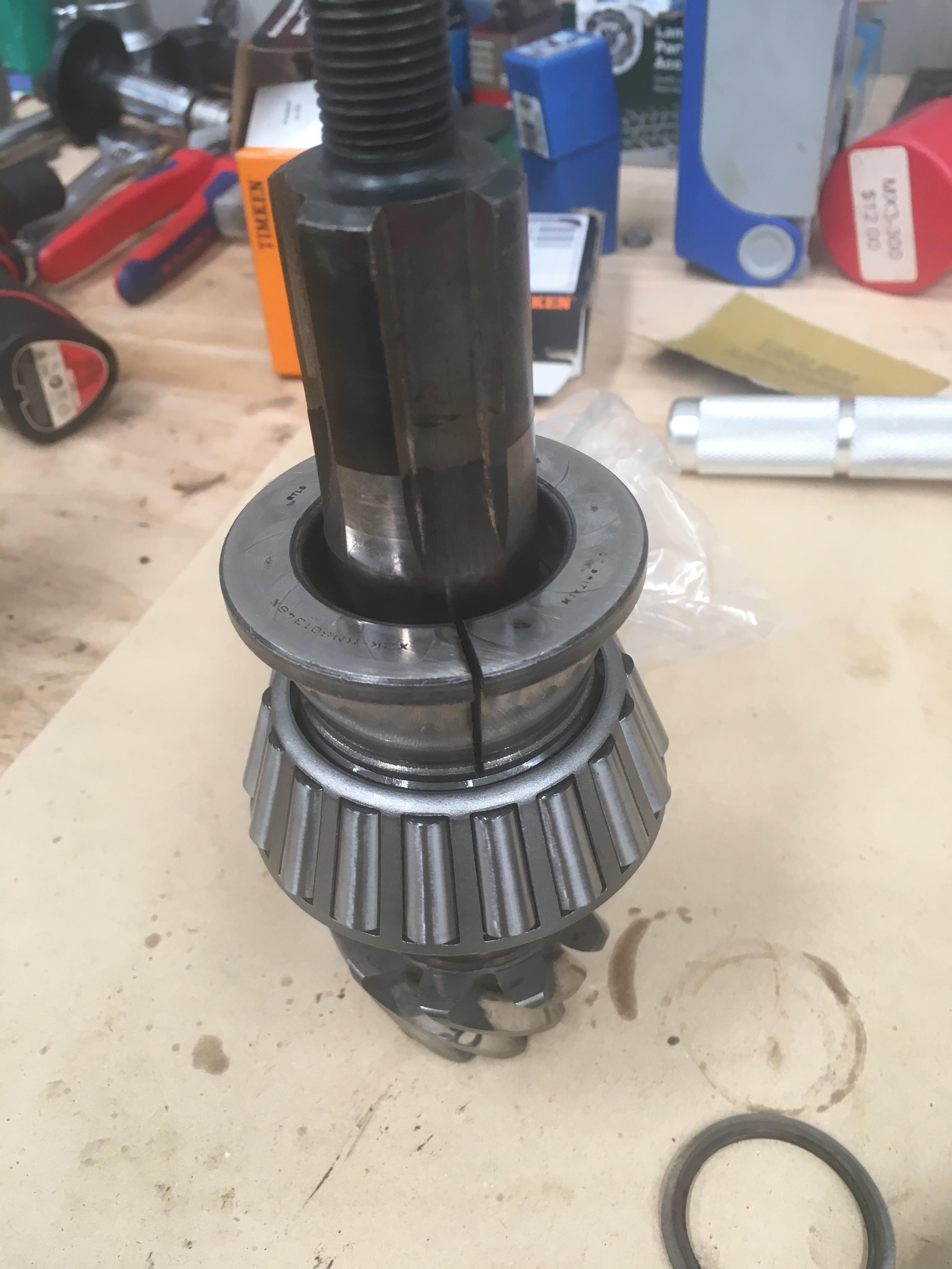
Whilst things were waiting for their paint to dry, and various bolts were soaking in degreaser I started on the front diff. Which is actually the rear diff, because the new rear diff, the old front diff, is getting an upgrade, and going in the back because it has less wear than the rear diff. Also the front diff, which is the old rear diff, is getting the center from the spare diff as it is in better nick. Confused? Good, I am to.
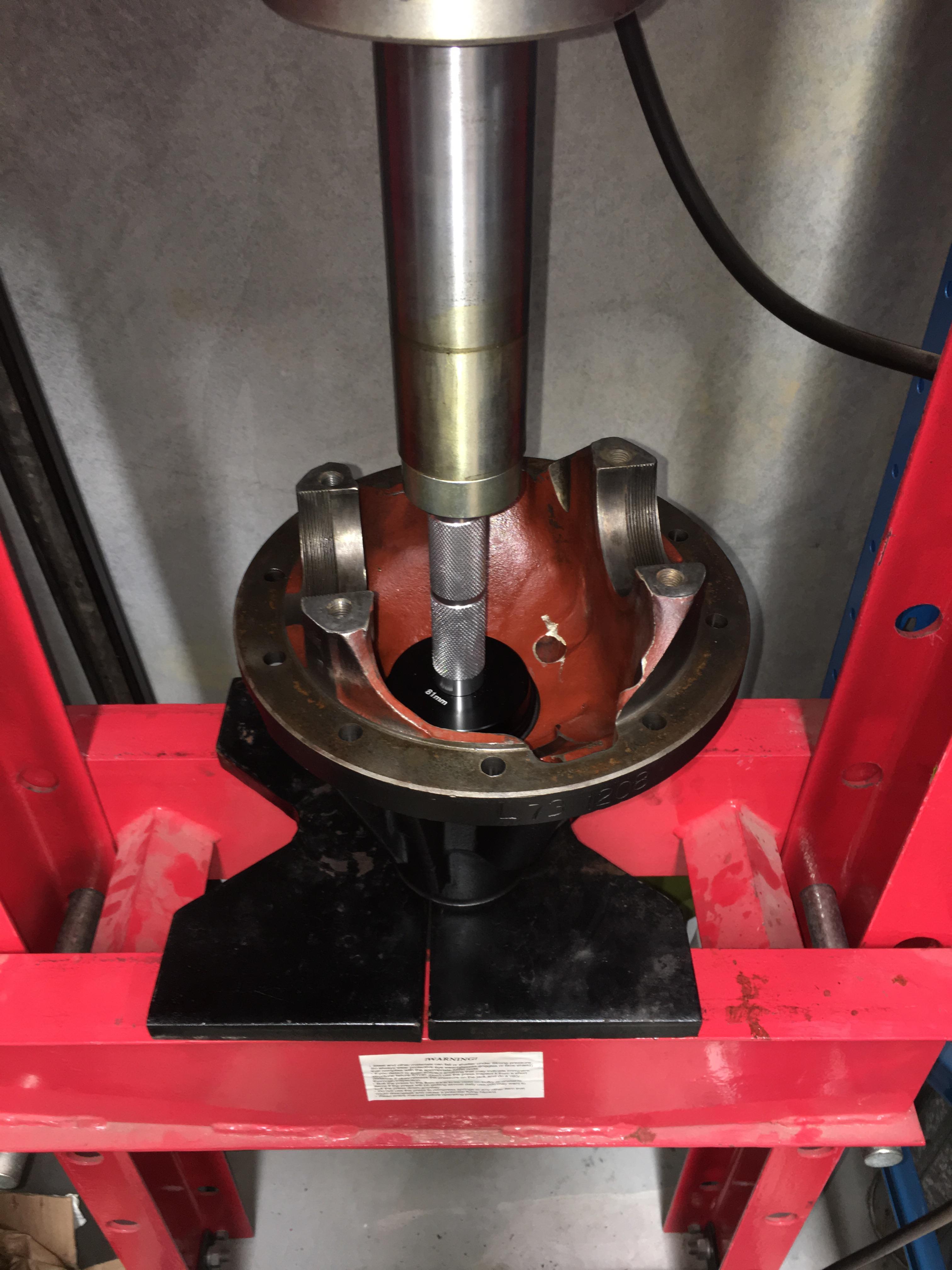
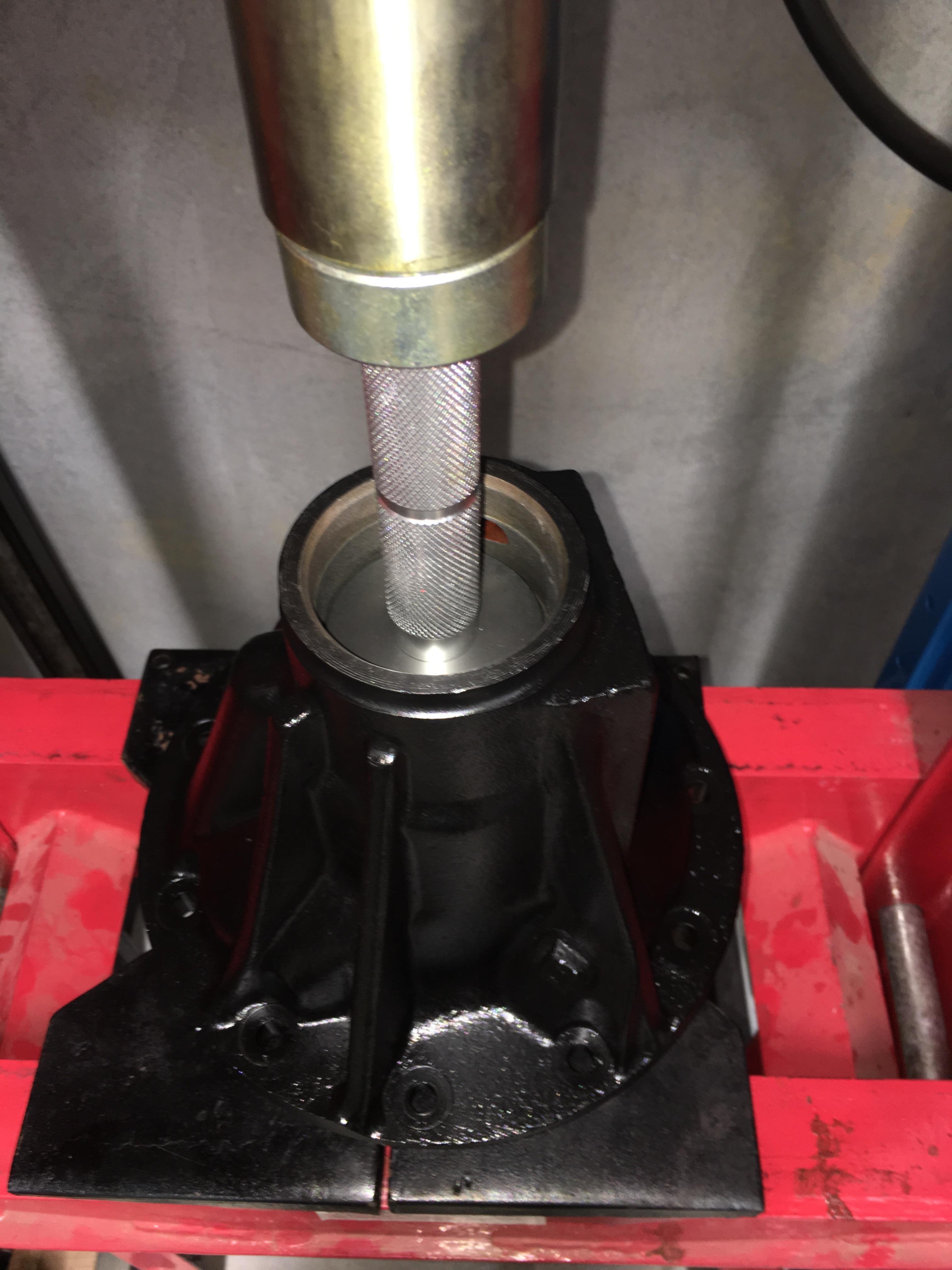
New pinion bearing shells getting pressed in
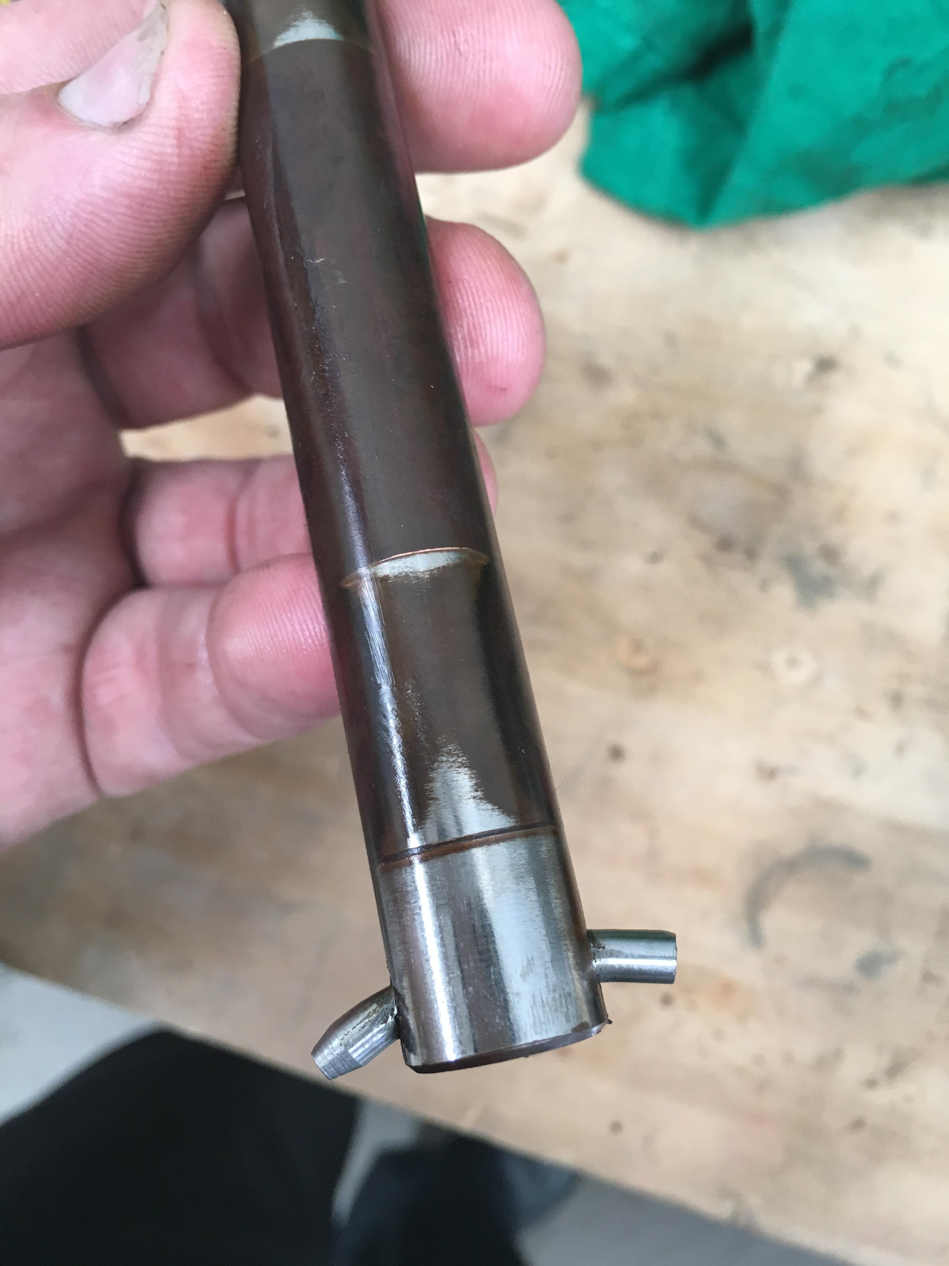
The donor diff center got stripped and cleaned. Little bit of wear on the cross pin, but not bad enough to warrant changing:
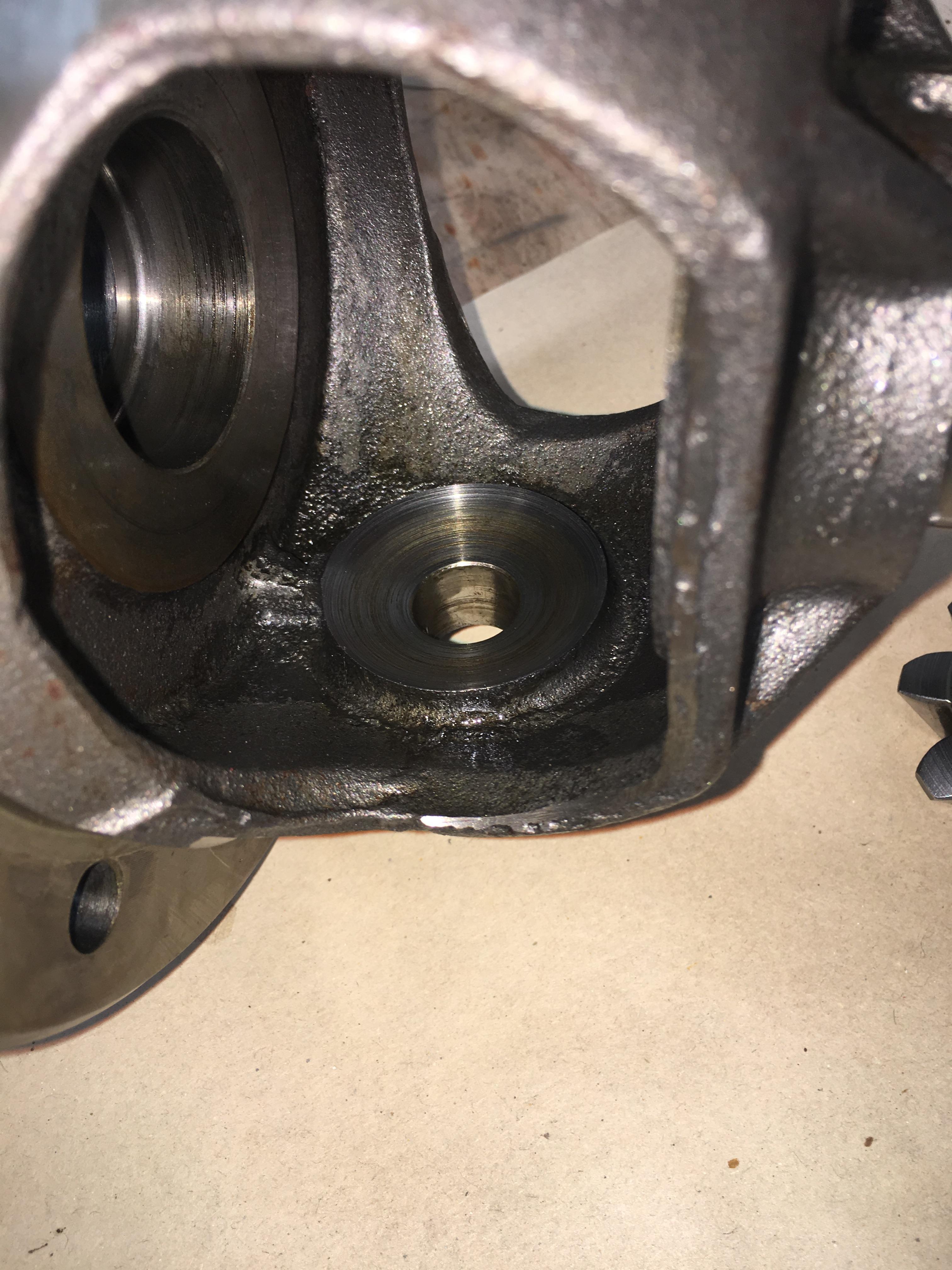
Little bit of wear to the housing, but the sun/planet gears were still quite tight:
All the bits cleaned and ready for reassembly
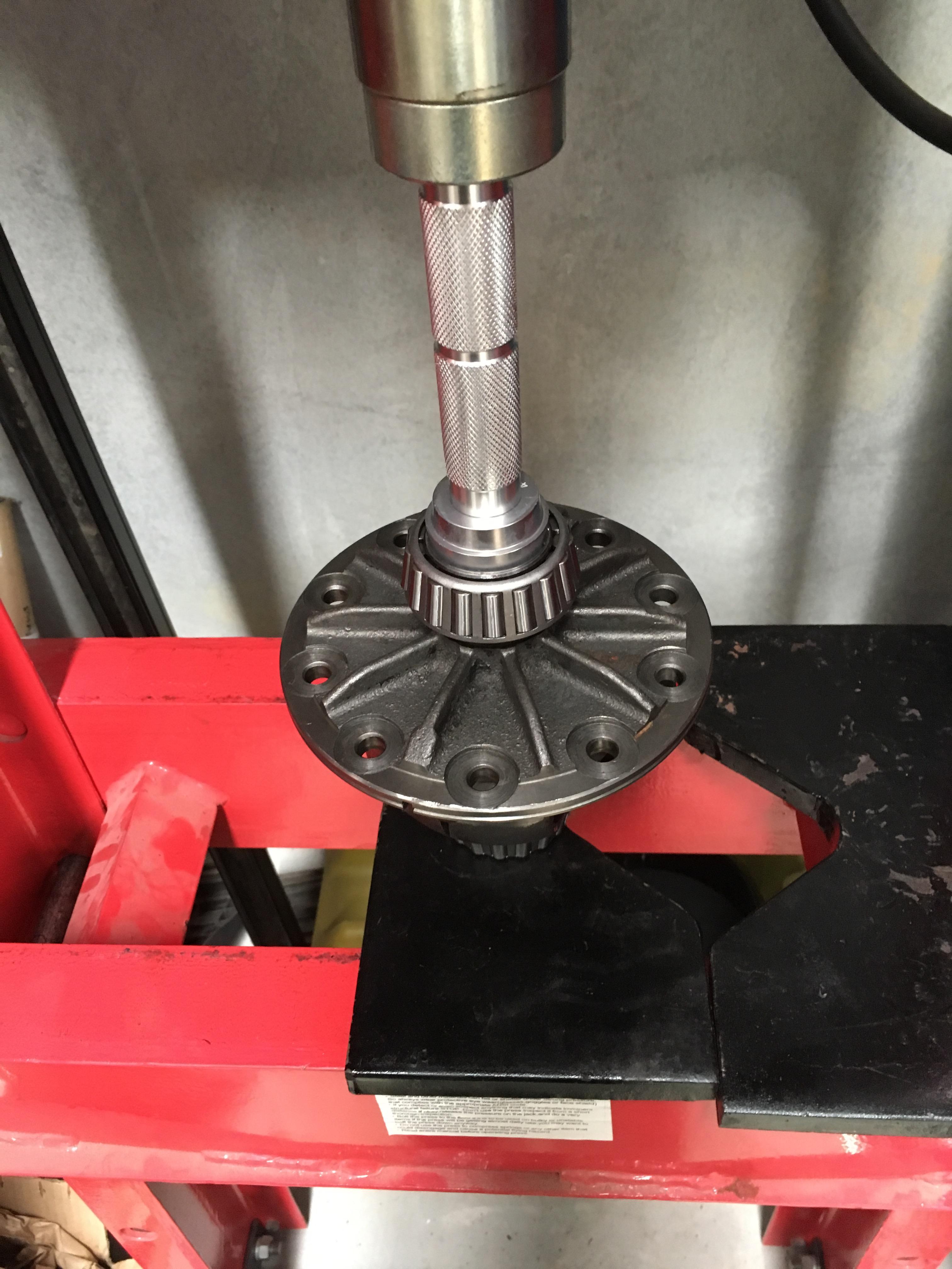
Bearings getting pressed on:
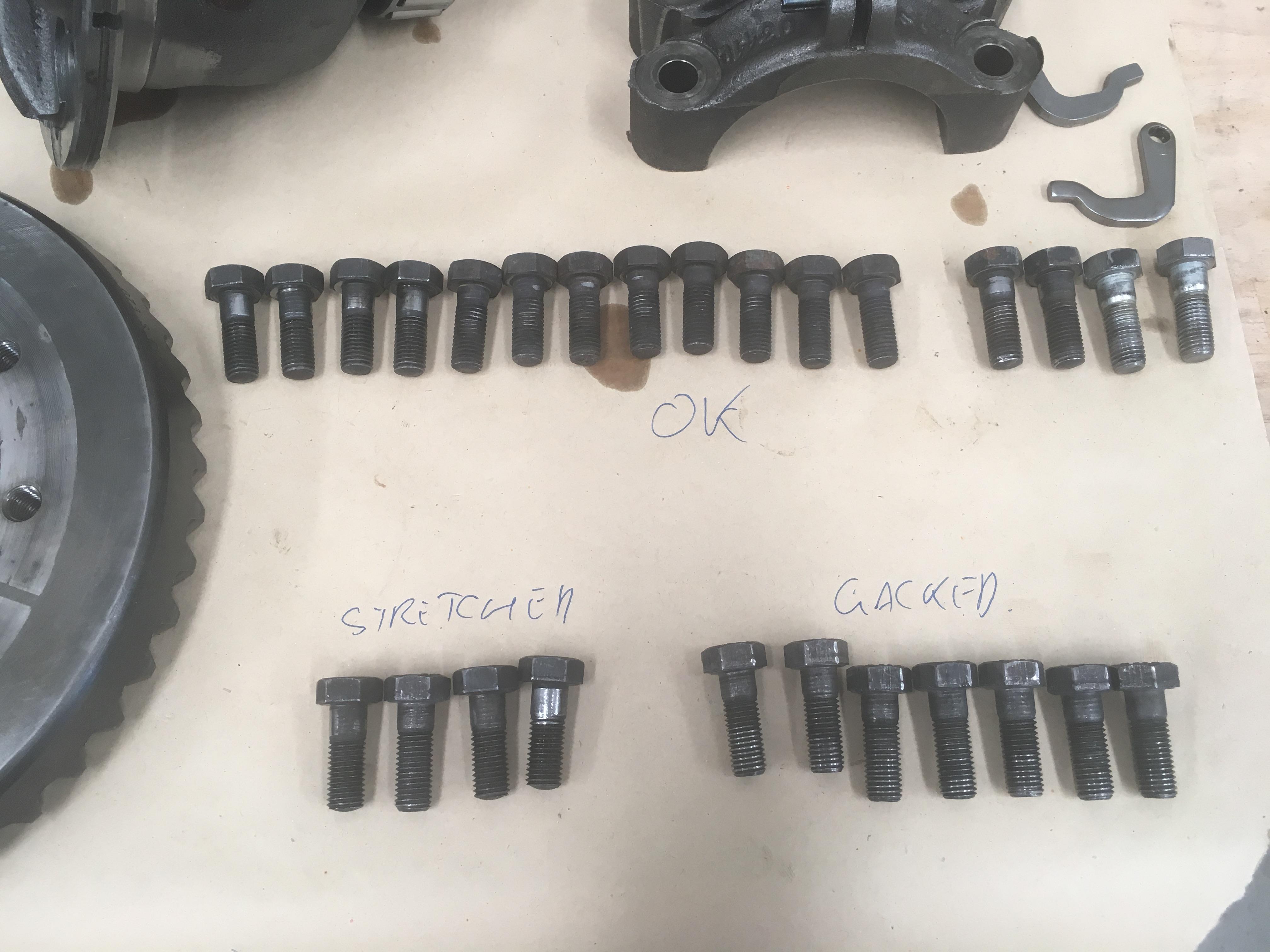
3 diffs worth of crown wheel bolts. The bolts on the front diff were also only finger tight, I think both diffs were done up with a "grunt twice" type torque wrench. As you can see quite a few of the bolts are stretched or damaged. All the bolts from the donor diff were fine.
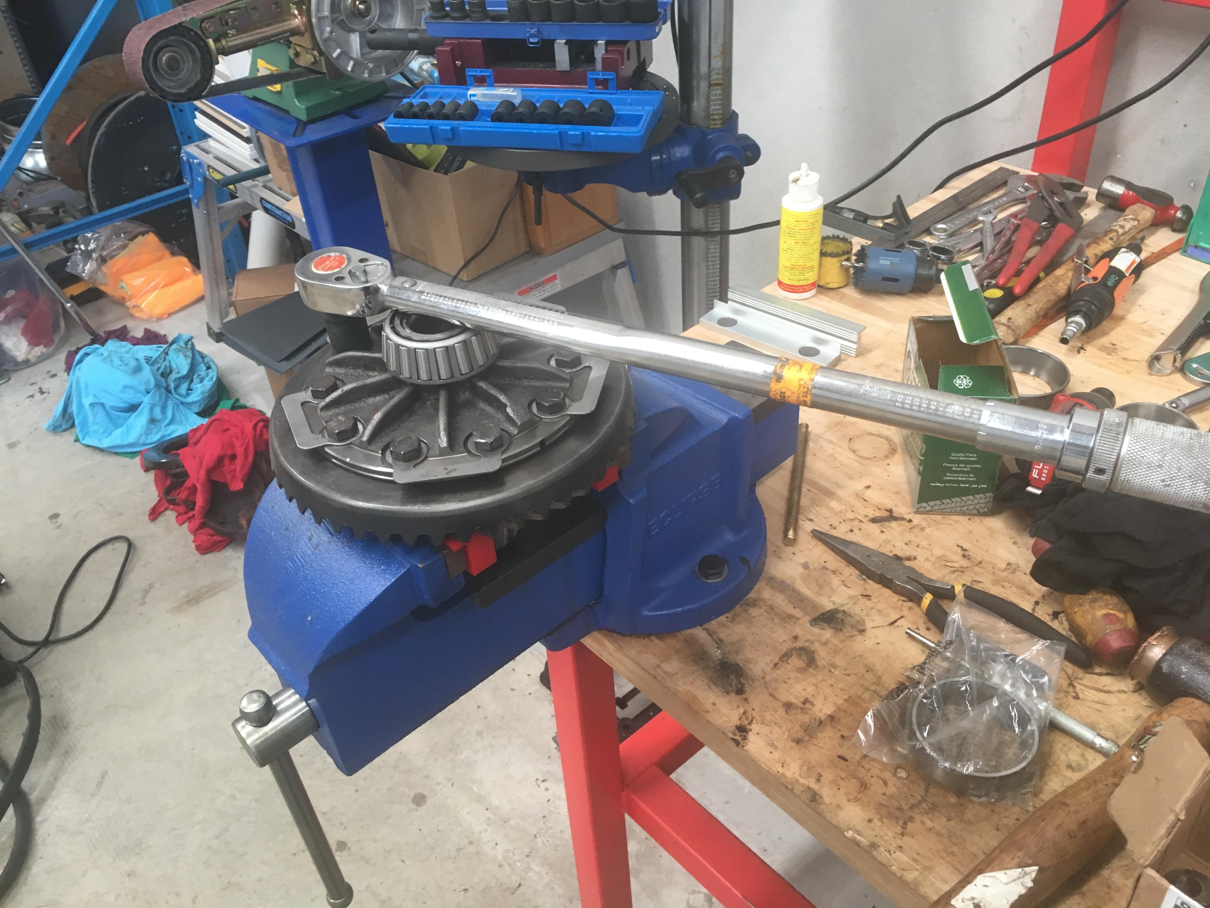
Crown wheel getting refitted, with an actual torque wrench.
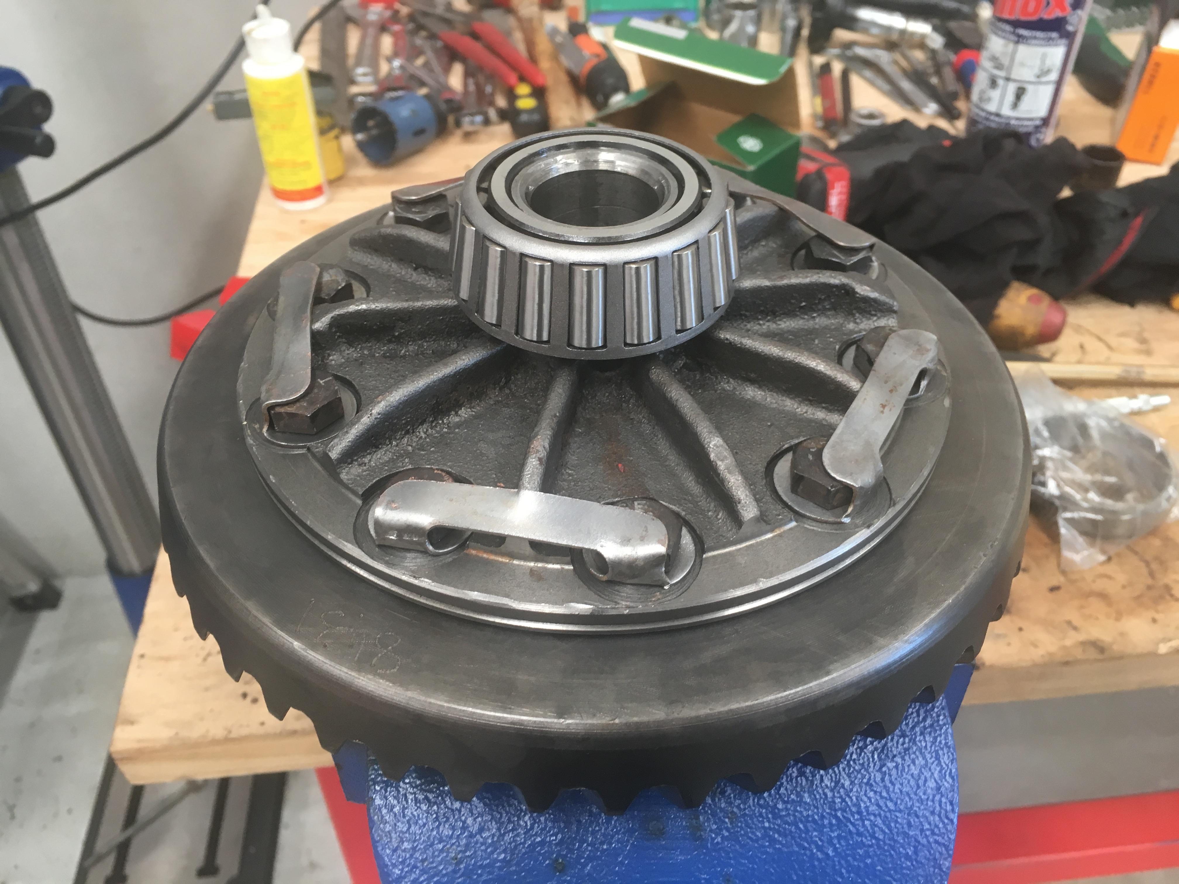
All done, lock tabs, (and loctite for good measure)
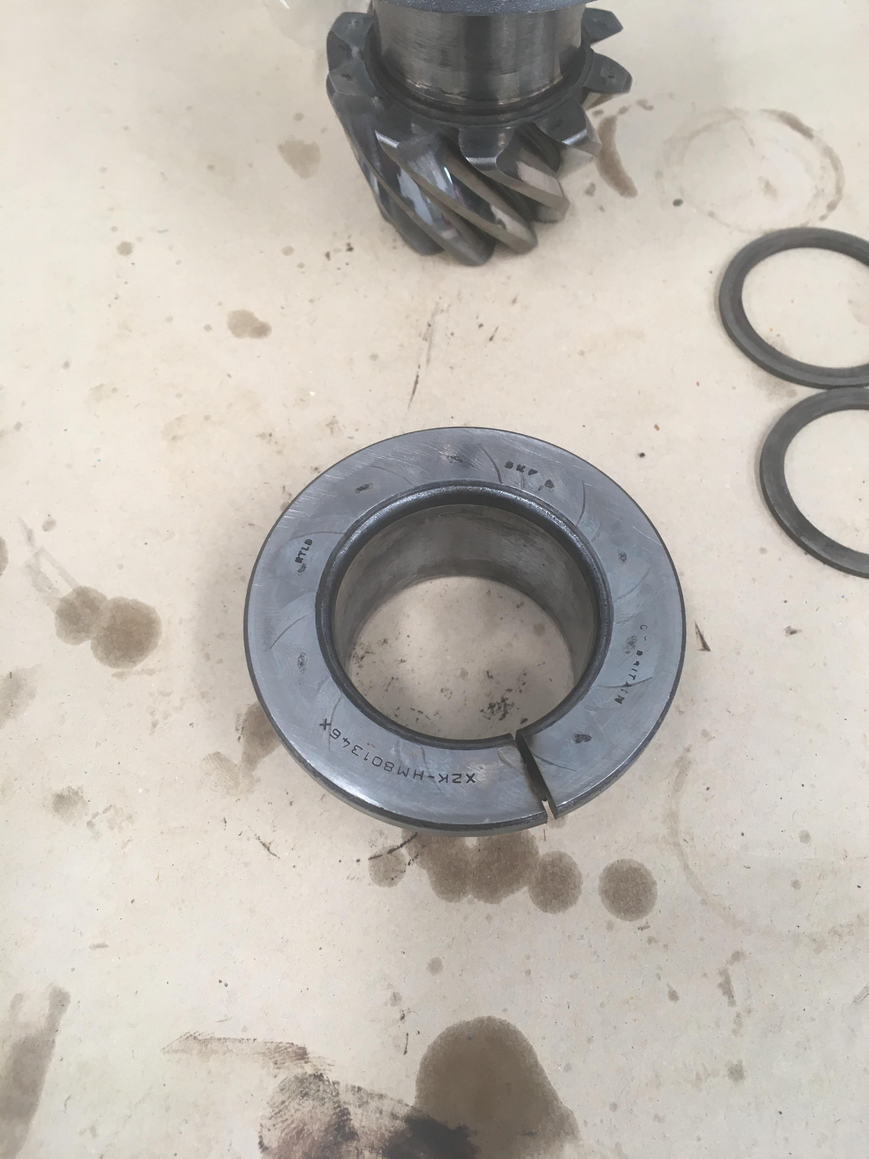
Modified the old pinion bearing into a pressing sleeve:
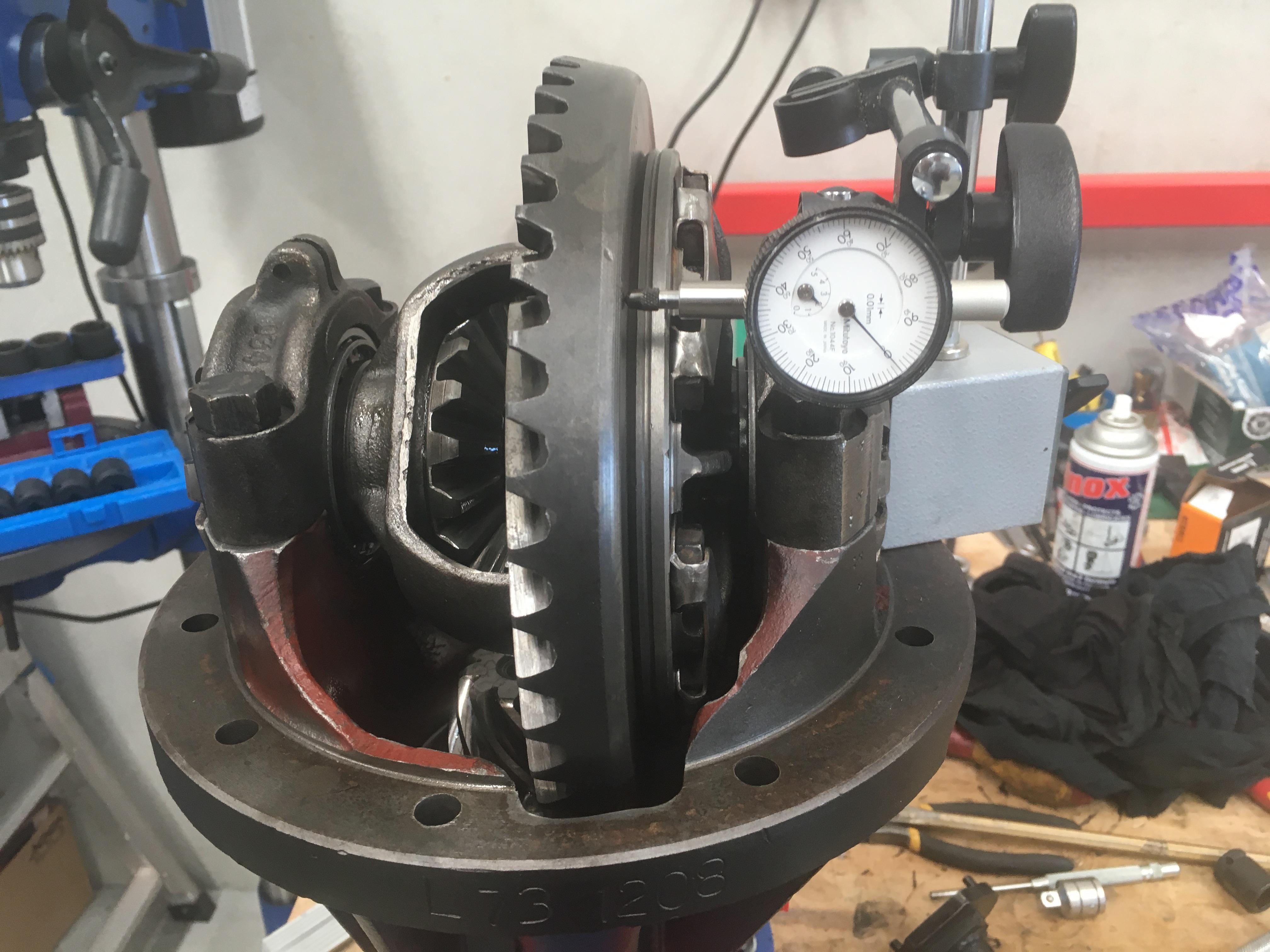
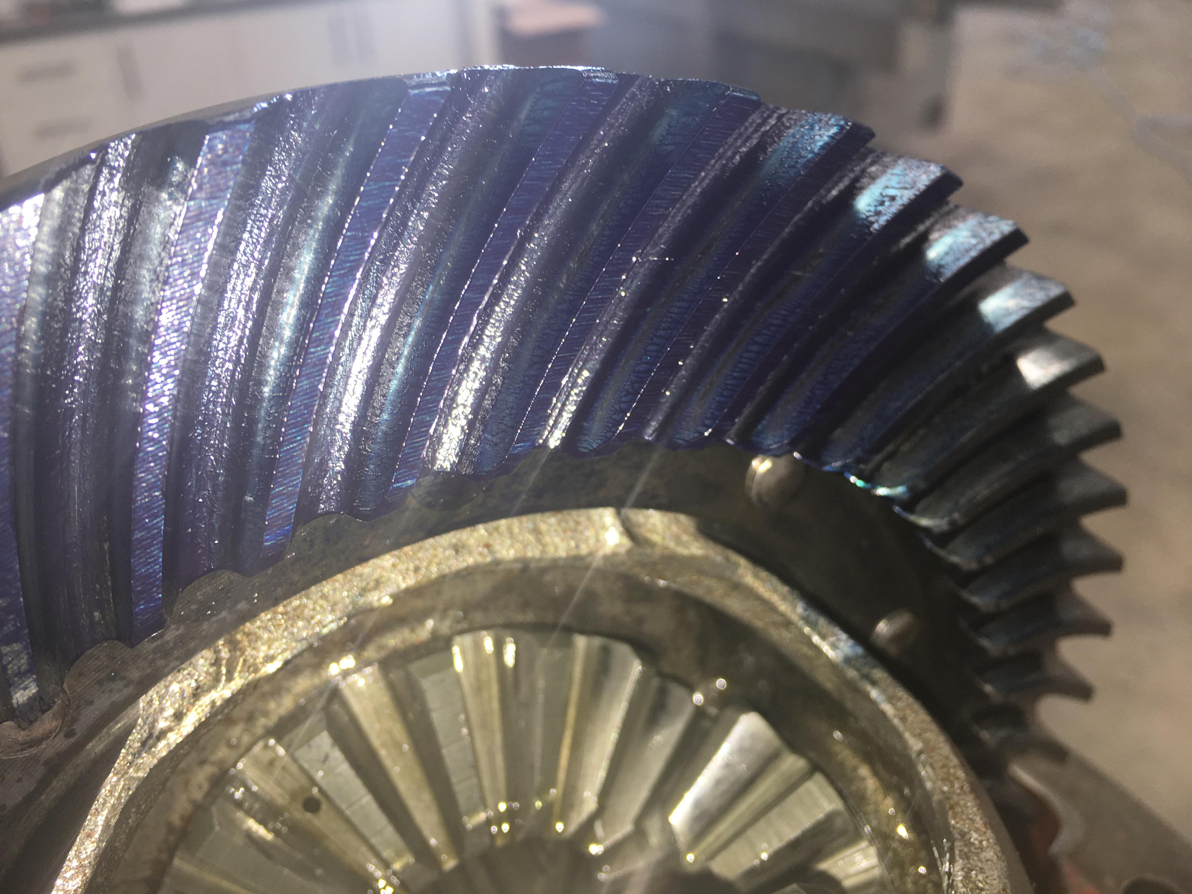
Diff going back together, checking the run out, (was 0.03mm)
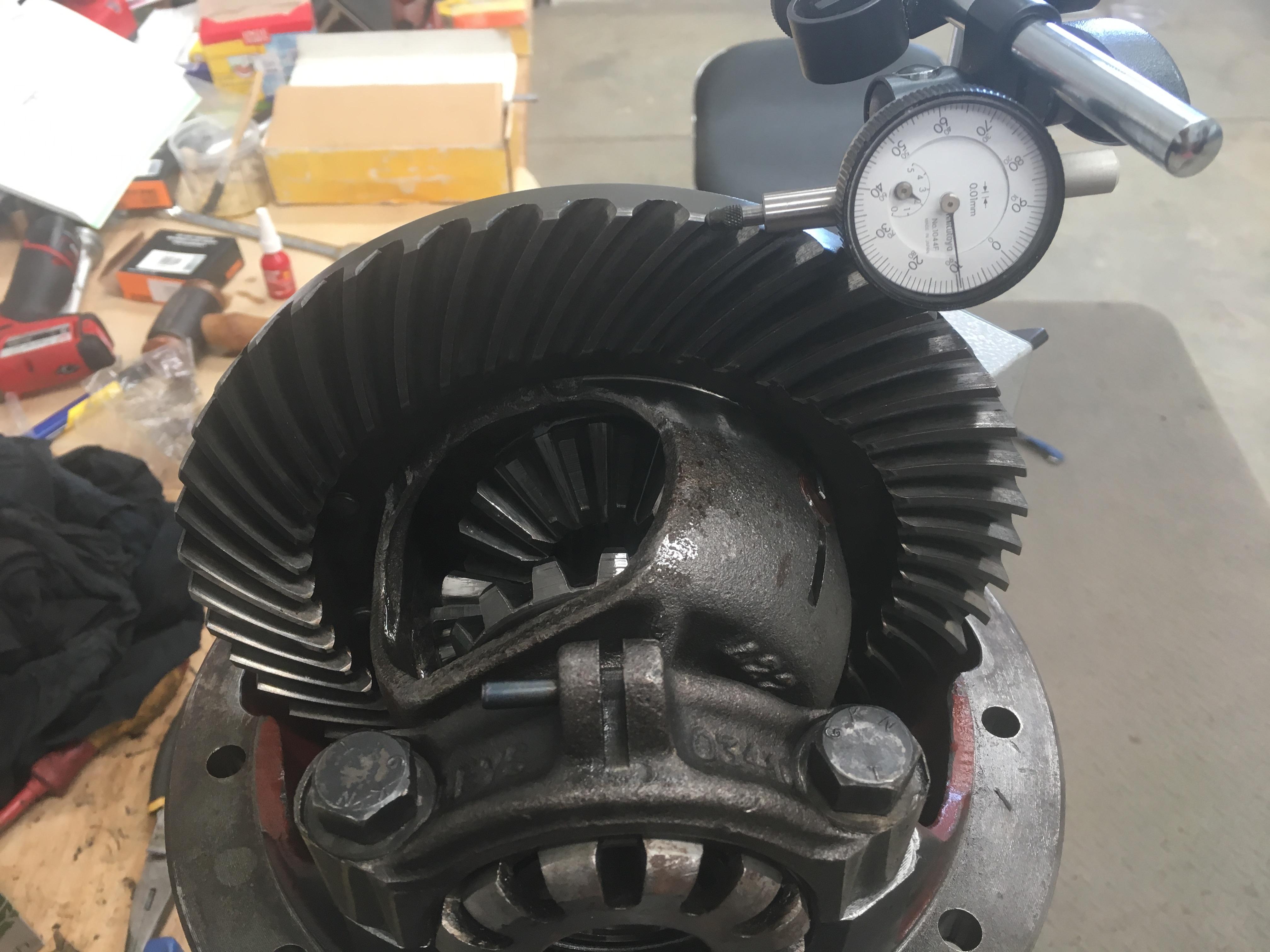
And back lash
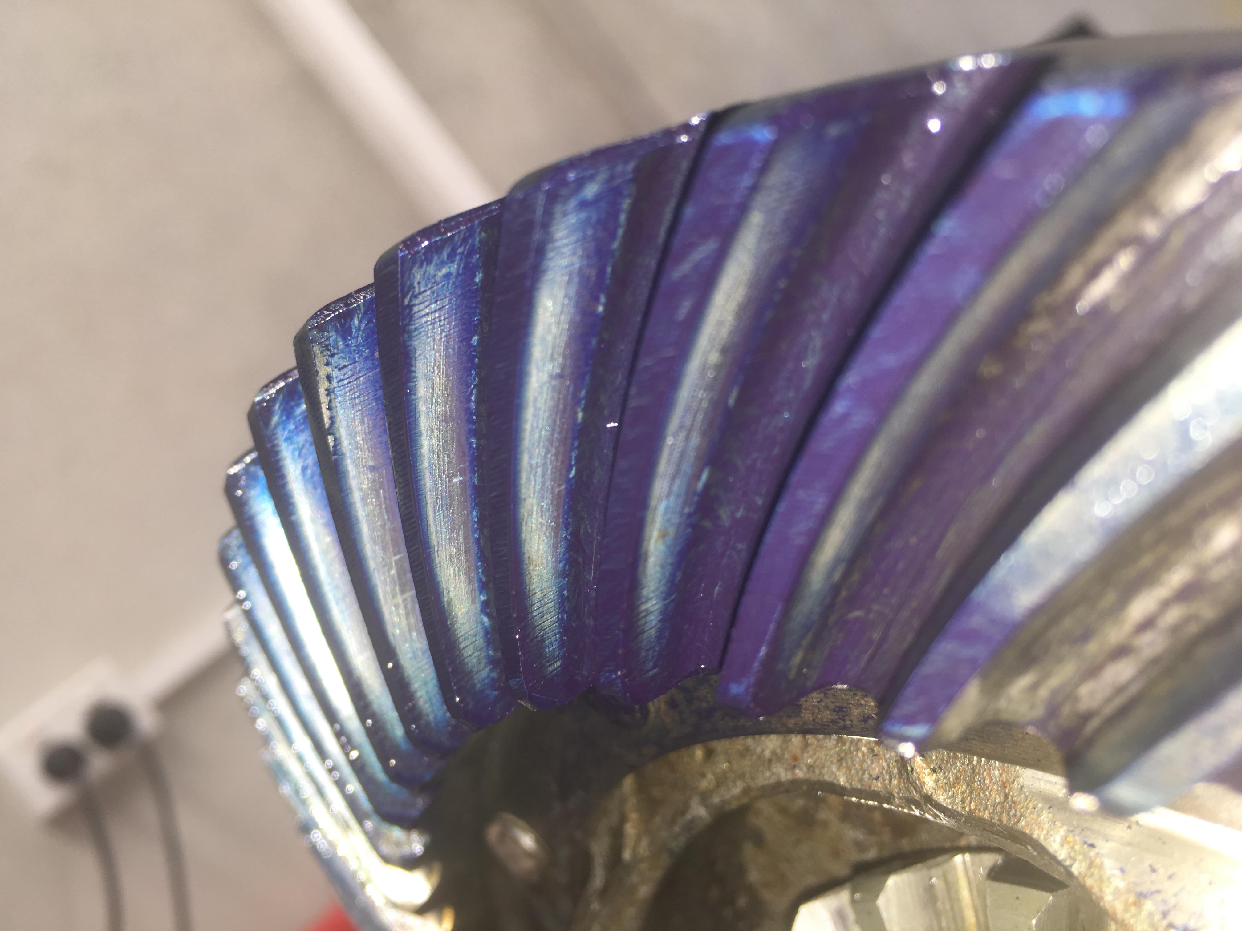
Tooth pattern on the coast side is OK
But to get an even contact on the drive side the back lash is way out to 0.4mm, and the contact is right in by the root of the teeth. I think I'll have to thin the pinion shimming down
I've put a thread about this in the technical section to get some advice.
And finally, more painting, yay.... Some of the new parts, (spring U bolts, swivel seal retainer etc), had the goldish anodising, that for one I don't really like, and two, is only good for preventing corrosion while parts are in storage. So they got a quick sandblast to provide a key for the paint, then some etch primer, (the KBS stuff).
Cheers,
 Posting Permissions
| Search AULRO.com ONLY! |
Search All the Web! |
|---|
|
|
|


Bookmarks